This article is about a simple auto ranging ohmmeter using arduino. The measured resistance is displayed using a 16×2 LCD display. The circuit is sufficiently accurate and uses minimum number of external components possible. Before going into the details of this project, lets have a look at the basic resistance measurement method.
Resistance measurement.
 The figure above shows the circuit diagram of a simple resistance measurement scheme. Rx is the resistance to be measured. R1 is the input resistance. i is the current passing through the loop and 5V is the supply voltage. To find the unknown resistance Rx, the voltage across Rx is measured first. let the voltage across R1 be VR1. Then VR1=5-Vx. The current i=VR1/R1=(5-Vx)/R1. Since R1 and Rx are connected in series, the current through them will be equal. So the unknown resistance Rx= Vx/i. The voltage across the unknown resistance is measured using the ADC of the arduino. To be precise, analog channel A5.
Anyway this method have a drawback. If there is great difference between the input resistance and the Rx, the result will be extremely inaccurate. This is because almost all of the input voltage will drop across the larger resistance and this provides very less information.
Suppose R1=10K and Rx=100 ohm. Then the voltage across R1 will be 4.95v and voltage across Rx will be 50mV and this gives less information. The sensitivity of the arduino is 4.889mV. So when we read 50mV using the arduino ADC the result will be 10. When converted it into voltage the result will be 10 x 4.889mV =48.89mV. Then Rx= 0.0488/((5V-48.89mV)/10000) = 98.7 ohm.
Suppose R1=10 and Rx=220 ohm. Then the voltage across R1 will be 4.89V and voltage across Rx will be 107mV. The corresponding digital reading will be 21. When we convert it into voltage the result will be 21 x 4.889mV=102mv. Following the calculations used in the previous case, Rx=208 ohm. In the above two cases you can see accuracy issues. The most accurate result occurs when the Rx and R1 are as close as possible.
Auto ranging.
 A scheme for estimating the value of Rx roughly and then putting a matching resistor in place of R1 is what we need here and this method is called auto ranging. The circuit given below demonstrates auto ranging.
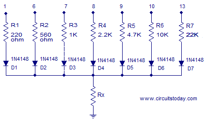
Resistances R1 to R7 are the input resistors. In this scheme the free end of one resistor is held high and the free ends of other resistors are held low. The the voltage across the unknown resistance Rx is measured. Diodes D1 to D7 are used to prevent the back flow of current towards the low ends. Suppose free end of R1 is held low. If R1 and Rx are equal, then the voltage drop across Rx will be (5-0.7)/2 = 2.15 where 0.7 is the diode drop. If the voltage across Rx is less than or equal to 2.15, we can assume that Rx is less than or equal to 220 ohms. The closest value possible for the input resistance is 220 ohms and so this loop is considered for calculation. If the above condition is not satisfied, the above steps are repeated with the succeeding input resistors until we get a solution.
Circuit diagram.

Full circuit diagram of the auto ranging ohmmeter using arduino is shown in the figure above. Digital pins 1, 6, 7, 8, 9, 10, 13 of the arduino are used to switch the input resistors R1, R2, R3, R4, R5, R6, R7 respectively. Resistors D1 to D7 are used to prevent the back flow of current through the corresponding path. D8 is the power ON indicator LED. POT R10 is used for contrast adjustment of the LCD. Resistor R9 limits the back light LED current.
Program.
#include<LiquidCrystal.h>
int vin=A5;
int t=1;
int u=6;
int v=7;
int w=8;
int x=9;
int y=10;
int z=13;

int at;
int au;
int av;
int aw;
int ax;
int ay;
int az;
int a;
double vx;
float rx;
double i;
LiquidCrystal lcd(12, 11, 5, 4, 3, 2);
void setup()
{
pinMode(vin,INPUT);
lcd.begin(16,2);

pinMode(t,OUTPUT);
pinMode(u,OUTPUT);
pinMode(v,OUTPUT);
pinMode(w,OUTPUT);
pinMode(x,OUTPUT);
pinMode(y,OUTPUT);
pinMode(z,OUTPUT);

digitalWrite(t,LOW);
digitalWrite(u,LOW);
digitalWrite(v,LOW);
digitalWrite(w,LOW);
digitalWrite(x,LOW);
digitalWrite(y,LOW);
digitalWrite(z,LOW);
}
void loop()
{

digitalWrite(t,HIGH);
digitalWrite(u,LOW);
digitalWrite(v,LOW);
digitalWrite(w,LOW);
digitalWrite(x,LOW);
digitalWrite(y,LOW);
digitalWrite(z,LOW);
delay(100);
at=analogRead(vin);


digitalWrite(t,LOW);
digitalWrite(u,HIGH);
digitalWrite(v,LOW);
digitalWrite(w,LOW);
digitalWrite(x,LOW);
digitalWrite(y,LOW);
digitalWrite(z,LOW);
delay(100);
au=analogRead(vin);
digitalWrite(t,LOW);
digitalWrite(u,LOW);
digitalWrite(v,HIGH);
digitalWrite(w,LOW);
digitalWrite(x,LOW);
digitalWrite(y,LOW);
digitalWrite(z,LOW);
delay(100);
av=analogRead(vin);


digitalWrite(t,LOW);
digitalWrite(u,LOW);
digitalWrite(v,LOW);
digitalWrite(w,HIGH);
digitalWrite(x,LOW);
digitalWrite(y,LOW);
digitalWrite(z,LOW);
delay(100);
aw=analogRead(vin);


digitalWrite(t,LOW);
digitalWrite(u,LOW);
digitalWrite(v,LOW);
digitalWrite(w,LOW);
digitalWrite(x,HIGH);
digitalWrite(y,LOW);
digitalWrite(z,LOW);
delay(100);
ax=analogRead(vin);


digitalWrite(t,LOW);
digitalWrite(u,LOW);
digitalWrite(v,LOW);
digitalWrite(w,LOW);
digitalWrite(x,LOW);
digitalWrite(y,HIGH);
digitalWrite(z,LOW);
delay(100);
ay=analogRead(vin);


digitalWrite(t,LOW);
digitalWrite(u,LOW);
digitalWrite(v,LOW);
digitalWrite(w,LOW);
digitalWrite(x,LOW);
digitalWrite(y,LOW);
digitalWrite(z,HIGH);
delay(100);
az=analogRead(vin);

if(az>=450)
{
vx=az*0.00489;
i=(5-vx-0.55)/22000;
rx=(vx/i);
}
if(ay>=450 && az<450)
{
vx=ay*0.00489;
i=(5-vx-0.55)/10000;
rx=(vx/i);
}
if(ax>=448 && ay<448 && az<448)
{
vx=ax*0.00489;
i=(5-vx-0.55)/4700;
rx=(vx/i);
}

if(aw>=439 && ax<439 && ay<439 && az<439)
{
vx=aw*0.00489;
i=(5-vx-0.55)/2200;
rx=(vx/i);
}

if(av>=439 && aw<439 && ax<439 && ay<439 && az<439)
{
vx=av*0.00489;
i=(4.8-vx-0.55)/1000;
rx=(vx/i);
}

if(au>=430 && av<430 && aw<430 && ax<430 && ay<430 && az<430)
{
vx=au*0.00489;
i=(4.5-vx-0.55)/560;
rx=(vx/i);
}

if(at>=430 && au<430 && av<430 && aw<430 && ax<430 && ay<430 && az<430 )
{
vx=at*0.00489;
i=(4.5-vx-0.55)/220;
rx=(vx/i);
}

if(at<430 && au<430 && av<430 && aw<430 && ax<430 && ay<430 && az<430 )
{
vx=at*0.00489;
i=(4.5-vx-0.55)/220;
rx=(vx/i);
}
lcd.setCursor(0,0);

if(vx>4.8)
{
lcd.clear();
lcd.setCursor(0,0);
lcd.print("----INFINITY----");
}
else
{
if(rx<1000)
{
lcd.clear();
lcd.setCursor(0,0);
lcd.print(rx);
lcd.setCursor(7,0);
lcd.print((char)244);
}
else
{
lcd.clear();
rx=rx/1000;
lcd.setCursor(0,0);
lcd.print(rx);
lcd.setCursor(6,0);
lcd.print("k");
lcd.print((char)244);
}
}
lcd.setCursor(0,1);
lcd.print("Arduino Ohmmeter");
}
sourse: www.circuitstoday.com
Comments
Post a Comment