12/16/2015

100W Subwoofer Amplifier Circuit

100W Subwoofer Amplifier Circuit

Subwoofer Amplifier Circuit Design

Audio Filter Design:
Here we designed a Sallen Key low pass filter using OPAMP LM7332. The cut off frequency was assumed to be 200Hz and the Quality factor is assumed to be 0.707.  Also assuming the number of poles to be equal to 1 and value of C1 to be equal to 0.1uF, value of C2 can be calculated to be 0.1uF.  Assuming R1 and R2 to be same, the value can be found by substituting known values in the equation
R1 = R2 = Q/(2*pi*fc*C2)
This gives a value of 5.6K for each resistor. Here we select 6K resistors as R1 and R2. Since we want a closed loop gain filter, we do not require resistors at the non inverting terminal, which is shorted to the output terminal.
Pre Amplifier Design:
The preamplifier is based on class A operation of transistor 2N222A.  Since the required output power is 100W and load resistor is 4 Ohms, here we require a supply voltage of 30V.
 Assuming the collector quiescent current to be 1mA and collector quiescent voltage to be half of supply voltage, i.e.15V, the value of load resistor is calculated to be equal to 15K.
R5 = (Vcc/2Icq)
Base current is given by, Ib = Icq/hfe
Substituting the values, hfe or AC current gain , we get the base current to be equal to 0.02mA. The bias current, Ibias is assumed to be ten times the base current, i.e. 0.2mA.
The emitter voltage is assumed to be 12% of the supply voltage, i.e. 3.6V. The base voltage, Vb is then equal to Ve +0.7, i.e. 4.3V.
Values of R3 and R4 are then calculated as given:
R3 = (Vcc – Vb)/ Ibias  and R4 = Vb/Ibias
Substituting the values, we get R3 to be equal to 130 K and R4 to be equal to 22K
The emitter resistor is calculated to be equal to 3.6K (Ve/Ie). However this resistance is shared between two resistors, R6 and R7, where R7 is used as feedback resistor to reduce the decoupling effect of C4.  Value of R7 is calculated by the values of R5 and gain and found to be equal to 300Ohms. Value of R6 is then equal to 3.2K.
Since capacitive reactance of C4 should be less than the emitter resistance, we calculate the value of C4 to be equal to 1uF.
Power Amplifier Design:
The power amplifier is designed using Darlington transistors TIP142 and TIP147 in class AB mode. The biasing diodes are selected such that their thermal properties are equal to that of the Darlington transistors. Here select 1N4007.
Since a large value of bias resistor is required for a low bias current, we select R9 to be equal to 3K.
The driver stage is used to provide a high impedance input to the power amplifier. Here we use a power transistor TIP41 in class A mode. The emitter resistor, R8 is given by the values of emitter voltage, Ve (1/2Vcc- 0.7) and emitter current, Ie (equal to collector current, i.e. 0.5A) and is found to be equal to 28.6 Ohms. Here we select a 30 Ohms resistor.
The value of bootstrap resistor R10 should be such that to be provide high impedance to the Darlington transistors. Here we select R10 to be 3K.

Subwoofer Amplifier Circuit Operation:

The audio signal is filtered by the Sallen Key low pass filter using the OPAMP such that only frequencies below and equal to 200Hz are passed and remaining filtered. This low frequency signal is given to the input of the transistor Q1 through the coupling capacitor, C3. The transistor operates in class A mode and produces a amplified version of the input signal at its output. This amplified signal is then converted into a high impedance signal by Q2 and is given to the class AB power amplifier.  The two Darlington transistors operate such that one conducts for positive half cycle and other for negative half cycle, thus producing a full cycle of output signal.  The emitter resistors R11 and R13 are used to minimize any difference between the matching transistors. The diodes are used to ensure minimal cross over distortion.  This high power output signal is then used to drive a loudspeaker or subwoofer of low impedance, about 4 Ohms. Note that here we have used an 8 Ohm resistor for testing purpose.

Applications of Subwoofer Amplifier Circuit:

  1. This circuit can be used at home theatre systems to drive subwoofers to produce a high quality, high bass music.
  2. This circuit can also be used as a power amplifier for low frequency signals.
Limitations of the Circuit:
  1. The filter circuit tends to increase the DC level of the audio signal, causing a disruption in the biasing.
  2. The use of linear devices causes power dissipation, thus reducing the efficiency of the circuit.
  3. It is a theoretical circuit and output contains distortion.
  4. The circuit doesn’t provide any provision to remove noise signal and thus the output may contain noisy disturbance.
Circuit Components:
COMPONENT
VALUE
R1
6K
R2
6K
R3
130K
R4
22K
R5
15K
R6
3.2K
R7
300 Ohms
R8
30 Ohms
R9, R10
3 K
C1, C2
0.1uF, electrolyte
C3,C5,C6
10uF, electrolyte
C4
1uF, electrolyte
Q1
2N222A
Q2
TIP41
Q3
TIP41
Q4
TIP147, PNP
D1, D2
1N4007
Dual Supply
+/-30V

How to match subwoofers and amplifiers

How to match subwoofers and amplifiers

The secret to great bass is making sure your subwoofers and amp are evenly matched and will properly work together. And this article will help you figure out how to do just that — match amplifiers and subwoofers. We cover the important basics of power-matching, impedance, and planning for the number of subs you want, and we approach the situation from both sides of the system:
  • Part A: You have the subs, which amp should you get?
  • Part B: You have the amp, which subs should you get?
Start with either part you want, but they're both worth a read.

Part A
You have the subs, which amp should you get?

The subs need to be the same
Multiple subs wired together must be the same coil type and impedance. If they’re not, the power won’t divide evenly between them, and some subs would probably be over-powered while others get under-powered. If you want to run different types of subs in a system, each type needs to have its own separate amp.

Step 1: How much power? Find out the “watts RMS” rating of the sub

Then, multiply the number of subs you have by the RMS rating of each, to get their total RMS rating. You want to make sure the amp you choose is capable of supplying from 75% to 150% of the sub system’s total RMS rating.

Step 2: What impedance? The results of combining coils and subs

Figure out the possible total impedance(s) that the subs can be wired together to form.
(SVC = single voice coil, 1 pair of terminals; DVC = dual voice coil, 2 pairs of terminals.)
  • 1 SVC 2-ohms can only have 2 ohms of impedance
  • 1 SVC 4-ohms can only have 4 ohms of impedance
  • 1 DVC 2-ohms can have 1 ohm or 4 ohms of impedance
  • 1 DVC 4-ohms can have 2 ohms or 8 ohms of impedance
  • 2 SVC 2-ohms can have 1 ohm or 4 ohms of impedance
  • 2 SVC 4-ohms can have 2 ohms or 8 ohms of impedance
  • 2 DVC 2-ohms can have 2 ohms or 8 ohms of impedance
  • 2 DVC 4-ohms can have 1 ohm or 4 ohms of impedance
  • 3 SVC 2-ohms can have 6 ohms of impedance
  • 3 SVC 4-ohms can have 1.3 ohms of impedance
  • 3 DVC 2-ohms can have 1.3 ohms or 3 ohms of impedance
  • 3 DVC 4-ohms can have 2.7 ohms or 6 ohms of impedance
  • 4 SVC 2-ohms can have 2 ohms or 8 ohms of impedance
  • 4 SVC 4-ohms can have 1 ohm or 4 ohms of impedance
  • 4 DVC 2-ohms can have 1 ohm or 4 ohms of impedance
  • 4 DVC 4-ohms can have 2 ohms or 8 ohms of impedance
 For more combinations of subs and their impedances, see Subwoofer Wiring Diagrams.

Step 3: Pick an amp that can do both — X watts at Y ohms

Look for an amplifier that can put out power within the RMS wattage range you’ve figured in Step 1, at an impedance load the subs can be wired to form, from Step 2.
Estimating amp power at the odd impedance values:
  • 8 ohms — figure on the amp putting out half the power it would at 4 ohms
  • 6 ohms — figure on the amp putting out three-quarters of the power it would at 4 ohms
  • 3 ohms — figure on the amp putting out the average of what it would at 2 ohms and at 4 ohms
  • 2.7 ohms — figure the same as for 3 ohms, and add a few watts
  • 1.3 ohms — use the 1-ohm spec and take away a few watts
Alpine Type R SWR-843D

Example:
You have two Alpine Type R SWR-8D4 8" subwoofers and you want the right amp for them.

They are DVC 4-ohm subs rated at 350 watts RMS each.
Two 350 watts RMS subs together need a total of 700 watts RMS, but an amp putting out from 525 to 1050 watts RMS will do. (75% of 700 is 525; 150% of 700 is 1050.)
Using the chart in Step 2, 2 DVC 4-ohm subs can be wired together to form a 1-ohm, a 4-ohm, or a 16-ohm load.
The last is too high a load to be practical, so you’ll look for an amp that can put out from 525 to 1050 watts RMS into either a 4-ohm load, or a 1-ohm impedance load:
  • (525-1050) watts RMS x 1 at 4 ohms, or
  • (525-1050) watts RMS x 1 at 1 ohm
Among Crutchfield’s selection of amplifiers you’ll find:
Any one of these high-quality amplifiers would work well with those subs. It doesn’t matter which impedance an amp plays through — 600 watts RMS through a 4-ohm load produces the same volume as 600 watts RMS through a 1-ohm load.  Notice that the Rockford Fosgate Power T1000-1bdCP can play that pair of subs at 700 watts RMS or 1,000 watts RMS, if you want it louder, just by wiring them together differently.
Rockford Fosgate T1000-1bdCP
Rockford Fosgate T1000-1bdCP subwoofer amplifier
The last two amps listed above, the Focal 2300RX and the Rockford Fosgate Power T600-2, are 2-channel amps that happen to work with these two subs when bridged in 1-channel mode. But multi-channel amps are typically lower-powered than mono subwoofer amps, and usually can’t drive loads lower than 4 ohms when bridged.

Kicker DXA1000.1
Kicker DXA1000.1 subwoofer amplifier

Part B
You have the amp, which subs should you get?

Step 1: What can the amp do? Find the RMS ratings of the amp at different loads

Find the amp’s power, expressed in “watts RMS”, at 4 ohms, at 2 ohms, and, if it can, at 1 ohm. Pick the power you’d like to achieve. The load impedance (ohms) of that rating will be what you want your subs’ total impedance to be.

Step 2: How many subs do you want?

Divide the power you picked in Step 1 by the number of subs you want. This number is the target RMS rating for each of the subs you’ll choose.
  • Divide that target number by 1.5. This is the lowest RMS rating per sub that will work.
  • Divide that target number by 0.75 for the highest RMS rating per sub.

Step 3: What impedance does each sub need to be and how many voice coils?

Using the impedance you picked in Step 1 and the number of subs from Step 2, cross-reference the possible coil configurations that you can use: 
1-ohm2-ohms4-ohms
1 subDVC 2-ohmsSVC 2-ohms
DVC 4 ohms
SVC 4-ohms
DVC 2-ohms
2 subsSVC 2-ohms
DVC 4-ohms
SVC 4-ohms
DVC 2-ohms
SVC 2-ohms
DVC 4-ohms
3 subs(1.3 ohms)*
SVC 4-ohms
DVC 2-ohms
(3 or 2.7 ohms)*
DVC 2-ohms
DVC 4-ohms
(6 ohms)*
SVC 2-ohms
DVC 4-ohms
4 subsSVC 4-ohms
DVC 2-ohms
SVC 2-ohms
DVC 4 ohms
SVC 4-ohms
DVC 2-ohms
* Estimate amp power at the odd impedance values like in Part A, Step 3, above.

Step 4: Pick a sub that works for both — (SVC or DVC) X-ohms, Y watts RMS)

Look for subs that are rated within the wattage range you figured in Step 2, and are configured as you found in Step 3. This might sound confusing, so let's walk through an example and it'll make sense.
Kenwood Excelon X500-1
Kenwood Excelon X500-1 subwoofer amplifier

Example:
You have a Kenwood Excelon X500-1 amplifier and you want it to drive two subwoofers

The amp is capable of 300 watts RMS x 1 at 4 ohms and 500 watts RMS x 1 at 2 ohms.
Let’s say you choose to maximize the amp’s potential and want the system to put out 500 watts RMS. This means your subs have to be wired to form a total impedance of 2 ohms.
Two subs on a 500 watts RMS amp will want about 250 watts RMS each.
250 divided by 1.5 is 167; 250 divided by 0.75 is 333. So you’ll look for subs each rated between 167 and 333 watts RMS.
Using the chart in Step 3, for two subwoofers, a final 2-ohm load can be achieved with either two SVC 4-ohm subs or two DVC 2-ohm subs.
So, you’ll look for two subs that are either SVC 4-ohms or DVC 2-ohms, rated between 167 and 333 watts RMS each:
  • 2 SVC 4-ohms, (167-333) watts RMS, or
  • 2 DVC 2-ohms, (167-333) watts RMS
Among Crutchfield’s selection of subwoofers you’ll find:
Kicker CompD 10"
Kicker CompD 10" component subwoofer
All these subwoofers will sound their best when amplified with the proper amount of power. Differences in size have more to do with tonal qualities and frequency response than with power performance. And optimizing performance is the point of matching subs and amps together.

11/25/2015

200 Watts Amplifier Circuit

200 Watts Amplifier Circuit connecting two TDA2030 thru cheap power transistors we can create a amplifier wich can deliver a higher power. With the components value from the schematic the total amplifier gain is 32 dB. The speaker can be 2 ohm instead of 4 ohm if we use the TIP transistors.
TDA 2030 is produced by SGS Ates and is a complete audio amplifier. AB class of the final amplifier cand deliver up to 14W on 4 ohm at a +-14V power supply. With a proper designed power supply this audio amplifier can output 200W.
200 Watts Amplifier Circuit


Active components:
  • IC1, Ic2 TDA 2030
  • T1, T3 = BD 250, TIP 36
  • T2,T4 = BD 249, TIP 35
  • D1 … D4 = 1N4001

Portable Mphone Preamplifier Circuit Schematic

Portable Mphone Preamplifier Circuit Schematic
The circuit is based on a low noise, high gain two stage PNP and NPN transistor amplifier, using DC negative feedback through R6 to stabilize the working conditions quite precisely. Output level is attenuated by P1 but, at the same time, the stage gain is lowered due to the increased value of R5. This unusual connection of P1, helps in obtaining a high headroom input, allowing to cope with a wide range of input sources (0.2 to 200mV RMS for 1V RMS output).
This circuit is mainly intended to provide common home stereo amplifiers with a microphone input. The battery supply is a good compromise: in this manner the input circuit is free from mains low frequency hum pick-up and connection to the amplifier is more simple, due to the absence of mains cable and power supply. Using a stereo microphone the circuit must be doubled. In this case, two separate level controls are better than a dual-ganged stereo potentiometer. Low current drawing (about 2mA) ensures a long battery life.
Portable Mphone Preamplifier Circuit Schematic

  • P1 = 2.2K
  • R1 = 100K
  • R2 = 100K
  • R3 = 100K
  • R4 = 8.2K
  • R5 = 68R
  • R6 = 6.8K
  • R7 = 1K
  • R8 = 1K
  • R9 = 150R
  • C1 = 1uF-63V
  • C2 = 100uF-25V
  • C3 = 100uF-25V
  • C4 = 100uF-25V
  • C5 = 22uF-25V
  • Q1 = BC560
  • Q2 = BC550

11/17/2015

200W Audio Amplifier Circuit Diagram

200W Audio Amplifier Circuit Diagram 
This audio amplifier circuit delivers up to 200 W of top-class quality for loudspeaker from 4 to 16 ohm. Operating voltage is between 24 and 36 V, max 5 A. The frequency response is from 20 to 20000 Hz.
Please take special care that the transistors and the IC’s have been fixed firmly and solely one or two separated cooling elements with sufficient dimensions for this purpose (thermal resistance < 1K/W).
Doing so it is necessary to mount the transistors and the IC’s insulated (with mica washes and plastic nipple). Please make sure before first operation that the transistors and the IC’s really do not have any electrical connection towards the cooling plate! The transistors have to be placed plane and firmly onto the cooling element! It is of extraordinary importance with this high-power amplifier that there is a considerable heat dissipation. The already mounted cooling element should be situated in a well ventilated case.
The PSU should be sufficiently powerful, power consumption of the amplifier may increase up to 5A. In case of using an unstabilised power supply. It is advisable to place a transformer of max 28V.

200W Audio Amplifier Circuit Diagram
200W Audio Amplifier Circuit Diagram 

The amplifier will the show approx. 120W at a 4-Ohm loudspeaker, for it no-load voltage of the power supply will not be to high. If it is desired to use complete power, it is necessary to place a stabilised power supply with approx. 36V 5A. No-load voltage should not pass over 44V!
The cables leading the current supply and to the loudspeakers should have at least a cross section of min. 1.5 mm^2. The connected loudspeaker have to be equiped according to the high output power and should not have a lower impedance as 4 Ohm! With lower connection impedance and short circuit within the loudspeaker wiring, the transistors will be destructed.
The amplifier has an input sensitivity of approx. 500 … 800 mV. Therefore, it is possibile to connect directly at the amplifier tape decks, tuners, etc. In case there are connected signal sources with lower output voltage, it is necessary to pre-connect a preamplifier. Then it will alse be posible to connect microphones, etc.

200W Audio Amplifier Circuit Diagram  Components

IC1, IC2 = 2 IC’s TDA2030
T1, T3 = 2 transistors KT818 or BD708
T2, T4 = 2 transistors KT819 or BD705
C1, C2, C3, C4, C7 = 5 capacitors 150 nF
C5 = 1 elca 10uF 63V
C8 – 1 capacitor 1.8 nF
R1, R7, R9 = 3 resistances 100K
R2, R3, R10, R11 = 4 resistances 2.2 Ohm
R4, R5 = 2 res. 2K
R6, R8 = 2 res. 1 Ohm
R12, R13 = 2 res. 2 res. 3.3K
D1…D4 = 1N4001, 1N4002, 1N4003
1 PCB board approx 56×51 mm

10/06/2015

18W Class-B Audio Amplifier with Tone Controls

18W Class-B Audio Amplifier with Tone Controls
General Description for 18W Class-B Audio Amplifier with Tone Controls
The particular circuit configuration, allowed to push the NE5534 exceptional capacity of driving the output transistors near to its limits, enabling the whole amplifier to deliver relatively high power outputs without problems. Despite the complication added by the tone controls, the amplifier has an input sensitivity of 130mV RMS, allowing to connect directly to its input the most disparate audio sources without the need for a separate preamplifier. For this reason, it was possible to obtain 18W into an 8 Ohm load using a power supply voltage of +/- 20V. In order to satisfy repeated requests by correspondents, a medium power audio amplifier incorporating tone controls in the feedback path was finally designed.Total Harmonic Distortion figures are astonishingly low, much lower than comparable audio amplifiers using a single-IC audio amp. To avoid an excessive increase in parts-count, due to the addition of the tone controls, a simple amplifier circuitry was designed on the same guidelines of the successful 45 Watt Class B Amplifier, but using the excellent NE5534 IC instead of a discrete component op-amp to drive the output "dumper" transistors. An interesting feature of this amplifier is the absence of any kind of setup.

Parts for 18W Class-B Audio Amplifier with Tone Controls

P1______________50K  Log. Potentiometer (or 47K)
                     (twin concentric-spindle dual gang for stereo)
P2______________20K  Linear Potentiometer (or 22K)
                     (twin concentric-spindle dual gang for stereo)
P3_____________100K  Linear Potentiometer
                   (twin concentric-spindle dual gang for stereo)
R1_____________820R  1/4W Resistor
R2______________68R  1/4W Resistor
R3_______________1K8 1/4W Resistor
R4______________10K  1/4W Resistor
R5_______________1K  1/4W Resistor
R6,R7__________100R  1/4W Resistors
R8_____________330R  1/4W Resistor
R9______________47R  1/2W Resistor
C1_______________1µF  63V Polyester Capacitor
C2______________33pF  63V Polystyrene or Ceramic Capacitor
C3______________10nF  63V Polyester Capacitor
C4,C5____________1nF  63V Polyester Capacitors
C6_____________120nF  63V Polyester Capacitor
C7______________22nF  63V Polyester Capacitor
C8,C10_________220nF  63V Polyester Capacitors
C9______________22µF  25V Electrolytic Capacitor
C11,C12________220µF  25V Electrolytic Capacitors
IC1__________NE5534   Low noise Single Op-amp
Q1____________BD440   60V 4A PNP Transistor
Q2____________BD439   60V 4A NPN Transistor
J1______________RCA audio input socket


7/13/2015

Electronics Tutorial #1 - Electricity - Voltage, Current, Power, AC and DC


Basic / beginners Electronics Tutorial / course / lesson - Voltage, Current, Power, AC and DC
--------------------- Click "Show more" -------------------------------
My website and forum:- http://www.mjlorton.com
Donations and contributions:- http://www.mjlorton.com
My techie channel MJLorton - Solar Power and Electronic Measurement Equipment -http://www.youtube.com/MJLorton
My Techie Amazon Store: http://astore.amazon.com/m0711-20
My other channel VBlogMag - For almost any topic under the sun! - http://www.youtube.com/VBlogMag
My VBlogMag Amazon Store: http://astore.amazon.com/vblogmag-20
----------------------------------------­-------------------------------

Nikola Tesla - http://en.wikipedia.org/wiki/Nikola_T...
Thomas Edison - http://en.wikipedia.org/wiki/Thomas_E...

In this tutorial I cover the following:

* Some history about electricity / central power stations / electrification. 
* Science of electron flow in a conductor / wire
* I use fluid dynamics in a pipe to explain voltage (pressure), current in Amps (flow) and consumption in Amp hours (rate of flow).
* We look at AC (alternating current) and DC (direct current) on the UNI-T UT81B scopemeter
* We look at how voltage / pressure is required to charge a 12 volt battery
* What is electricity? / How does electricity work?

Topics for future videos in this series:

* Ohms law, resistance, power, energy
* Electronic components - diodes, transistors, FETS, capacitors, digital logic gates, integrated circuits, 555 timer.
* Series and parallel circuits
* Op amps and feedback

7/10/2015

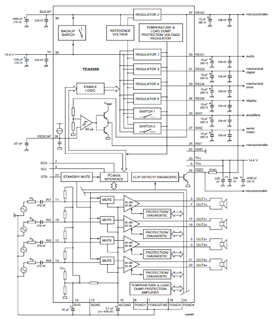
Power Amplifier with voltage regulator 4 × 50 Watt TDA8588

Power Amplifier with voltage regulator 4 × 50 Watt TDA8588
   The TDA8588 is a multiple voltage regulator combined with four independent audio power amplifiers configured in bridge tied load with diagnostic capability. The output voltages of all regulators except regulators 2 and 3 can be controlled via the I2C-bus. However, regulator 3 can be set to 0 V via the I2C-bus. The output voltage of regulator 2 (microcontroller supply) and the maximum output voltage of regulator 3 (mechanical digital and microcontroller supplies) can both be either 5 V or 3.3 V depending on the type number. The maximum output voltages of both regulators are fixed to avoid any risk of damaging the microcontroller that may occur during a disturbance of the I 2C-bus. The amplifier diagnostic functions give information about output offset, load, or short-circuit. Diagnostic functions are controlled via the I2C-bus. The TDA8588 is protected against short-circuit, over-temperature, open ground and open VP connections. If a short-circuit occurs at the input or output of a single amplifier, that channel shuts down, and the other channels continue to operate normally. The channel that has a short-circuit can be disabled by the microcontroller via the appropriate enable bit of the I 2C-bus to prevent any noise generated by the fault condition from being heard.
Speaker protection
    If one side of a speaker is connected to ground, a missing current protection is implemented to prevent damage to the speaker. A fault condition is detected in a channel when there is a mismatch between the power current in the high side and the power current in the low side; during a fault condition the channel will be switched off. The load status of each channel can be read via the I 2C-bus: short to ground (one side of the speaker connected to ground), short to VP (one side of the speaker connected to VP), and shorted load.

Muting 
    A hard mute and a soft mute can both be performed via the I 2C-bus. A hard mute mutes the amplifier within 0.5 ms. A soft mute mutes the amplifier within 20 ms and is less audible. A hard mute is also activated if a voltage of 8 V is applied to pin STB. 

Temperature protection 
     If the average junction temperature rises to a temperature value that has been set via the I2C-bus, a thermal protection pre-warning is activated making pin DIAG LOW. If the temperature continues to rise, all four channels will be muted to reduce the output power (soft thermal clipping). The value at which the temperature mute control activates is fixed; only the temperature at which the thermal protection pre-warning signal occurs can be specified by bit D4 in instruction byte 3. If implementing the temperature mute control does not reduce the average junction temperature, all the power stages will be switched off (muted) at the absolute maximum temperature Tj(max)

Power Amplifier with voltage regulator 4 × 50 Watt TDA8588

Search This Blog

Powered by Blogger.

200W Audio Amplifier Circuit

Circuit description: Connecting two TDA2030 thru cheap power transistors we can create a amplifier wich can deliver a higher power. Wi...

Labels

Amplifier Circuits (107) 4 Ω (85) TDA Amplifiers (66) Amplifier (50) 8 Ω (46) Circuit (37) subwoofer (31) Layout (26) audio (26) Subwoofer circuit (25) 2 Ω (23) Class D (23) Subwoofer Amplifier (23) Description (22) PCB (21) Subwoofer Diagram (21) Audio Amplifier (20) Stereo Amplifier (18) 20W (17) Auto Subwoofer (17) Stereo Amp (16) car subwoofer (16) BTL amplifier (14) ClassAB (14) Software (14) Electronic software (13) Sound System (13) 2x10W (12) 4-channel (12) 60W (12) BTL audio amplifier (12) Car Audio (12) Operational Amplifier (12) Power Amplifier (12) 2x12W (10) Audio Power Amplifier (10) Car Stereo (10) 2x25W (9) 5W (9) Car Amplifier (9) Circuit Diagram (9) Dual channel (9) Filter Circuits (9) Speakers (9) 2x40W (8) 2x6W (8) 3W (8) 4x50W (8) Audio Power Amp (8) Class B (8) Guitar Amplifier (8) 10W (7) 2x22W (7) 4x35W (7) 50W (7) Car Stereos (7) Subwoofer car (7) car radio amplifier (7) mono amplifier (7) 100W (6) 12W (6) 1W (6) 2-channel (6) 22W (6) 2w (6) 2x20W (6) 2x30W (6) Features (6) Guitar circuits (6) Microphone (6) Mixer (6) Stereo Preamp (6) general description (6) quad bridge (6) tone control (6) 100W Audio Amplifier (5) 18W (5) 40W (5) 4W (5) 4x45W (5) 6 Ω (5) 70W (5) Amps (5) Audio Processor (5) Car radio (5) Diagram (5) MOSFET (5) Preamplifier (5) applications (5) hi-fi audio power amplifier (5) newamps (5) 15W (4) 2-channel Amplifier (4) 200W (4) 2x100W (4) 2x15W (4) 6W (4) 8W (4) Amplifier High-Performance (4) BTL stereo (4) Bridge Amplifer (4) Class T (4) Datasheet (4) Dual Preamplifier (4) Equalizer circuit (4) Quad power amplifier (4) STK Amplifier (4) Sound Amplifier Circuit (4) Volume Control (4) car radio power amplifier (4) stereo BTL (4) 100W Subwoofer (3) 24W (3) 2x200W (3) 2x50W (3) 3 Ω (3) 3-channel (3) 300W (3) 35W (3) 4-ch amplifier circuit diagram (3) 400W (3) 4x11W (3) 4x12W (3) 4x22W (3) 4x40W (3) 500W (3) 80W (3) AM/FM Tuner (3) Amp (3) Amplifer (3) Arduino (3) Audio Circuit Diagram (3) Audio Speakers (3) Audio signal processing (3) Car Speakers (3) DMOS (3) Digital Audio Amplifier (3) Dual Audio (3) Dual BTL (3) Graphic Equalizer (3) Guitar (3) Guitar Effect Circuit (3) Hi-Fi audio (3) LED (3) Low noise (3) Power Supply (3) STK412-000 (3) Stereo balance meter (3) Subwoofer Design (3) Surround (3) TDA (3) TDA1566 (3) TDA2008 (3) TDA8586 (3) Tips To Save Energy (3) digital controlled (3) guitars (3) single channel (3) stereo headphone (3) 100+100W (2) 1000W (2) 1000W Amplifier (2) 100W Subwoofer Amplifier Circuit (2) 14W (2) 180W + 180W (2) 1ch BTL Power Amplifier (2) 2 x 210 Watt (2) 200W amplifier (2) 25W (2) 28w (2) 2x110W (2) 2x11W (2) 2x120W (2) 2x150W (2) 2x1W (2) 2x210W (2) 2x24W (2) 2x300W (2) 2x35W (2) 2x46W (2) 2x5W (2) 2x7W (2) 2x80W (2) 3 channel amplifier (2) 30W (2) 30w Amplifier (2) 32 Ω (2) 32W (2) 45W (2) 4x13W (2) 4x25W (2) 4x30 (2) 4x6W (2) 4x70W (2) 5 Band Graphic Equalizer Circuit (2) 92W (2) AM receiver (2) AM/FM Radio (2) AN12941A (2) AN12972A (2) AN7110 (2) AN7163 (2) AN7177 (2) AN7531SA (2) ARM (2) ARM Microcontroller (2) Aliexpress circuits (2) Amplifier Transistors (2) Audio Filter Circuits (2) Audio Mixer (2) Audio Mixer Circuit (2) Audio Preamplifier (2) BCDMOS technology (2) BTL power amplifier (2) CMOS (2) Car Subwoofers (2) Ceiling Speakers (2) Class H (2) Equalizer (2) FM Stereo (2) FM Transmitter (2) Guitar Amps (2) Guitar circuit (2) HA13116 (2) Hi-Fi systems (2) IRF530 (2) IRF9530 (2) LA4460N (2) LM1875 (2) LM380 (2) LM3886 (2) LPC2124 (2) MOSFET Audio Amplifier (2) Microcontroller (2) Music System (2) NE5532 (2) NE555 (2) Peak Indicator (2) Power Amp (2) Recording (2) STA501 (2) STEREO (2) STK400-530 (2) Sound (2) Sound Decoder (2) Speaker (2) Stereo Decoder (2) Stereo Headphone Amplifier (2) TA8210AH Amplifier (2) TDA1015 (2) TDA1037 (2) TDA1083 (2) TDA1514A (2) TDA1517 (2) TDA1562Q (2) TDA1904 (2) TDA1905 (2) TDA1910 (2) TDA2003 (2) TDA2004 (2) TDA2051 (2) TDA2613 (2) TDA7056 (2) TDA7264 (2) TDA7269 (2) TDA7294 (2) TDA7298 (2) TDA7299 (2) TDA7334 (2) TDA7360 (2) TDA7454 (2) TDA7481 (2) TDA7490 (2) TDA7511 (2) TDA7850 (2) TDA8562Q (2) TDA8922 (2) TDA8924 (2) TDA8929T (2) TDA8931 (2) Two-channel Amplifier (2) best car speakers (2) demodulators FM (2) high performance hi-fi amplifier (2) partlist (2) quad bridge car radio amplifier (2) speaker protection (2) stereo car radio power amplifier (2) stereo tv (2) subwoofer circuit diagram (2) subwoofer for car (2) subwoofer preamp circuit diagram (2) subwoofers for cars (2) /Playback Pre-/Power Amplifier (1) 0.5W (1) 1 Ω (1) 1-channel (1) 1.2W (1) 1.6W (1) 10+10+10W (1) 1000 watts power amplifier schematic diagram (1) 1000W MOSFET (1) 100W Guitar Amplifier (1) 100W MOSFET (1) 10W circuit (1) 10W+10W (1) 1100W (1) 12 W car radio power amplifier (1) 1200W (1) 120W (1) 13.5W (1) 130W (1) 140 watt subwoofer (1) 140W (1) 14W+2x7.5W (1) 150 Amplifier (1) 150W (1) 150W+150W+150W (1) 170W amplifier (1) 17W (1) 18W Class-B Audio Amplifier (1) 19V (1) 1Kw Amplifier (1) 2 × 13 W (1) 2.1 channel (1) 2.7W (1) 200 Watts Amplifier Circuit (1) 200 watt mosfet amplifier circuit (1) 200W Audio Amplifier Circuit Diagram (1) 200W amplifier circuit (1) 200w stereo digital audio power amplifier (1) 20W+20W (1) 20W+20W+20W (1) 21W (1) 240W (1) 26 W BTL (1) 26V (1) 27W (1) 2SK1066 (1) 2x1.4W (1) 2x1.7W (1) 2x1100W (1) 2x13W+26W (1) 2x14W (1) 2x170W (1) 2x175W (1) 2x18W (1) 2x2.2W (1) 2x23W (1) 2x250W (1) 2x2W (1) 2x32W (1) 2x45W (1) 2x5.5W (1) 2x500W (1) 2x60W (1) 2x60mW (1) 2x7.3W (1) 2x70W (1) 2x75mW (1) 3 band equalizer guitar (1) 3-channel mixer (1) 30 Watt x 5 (1) 300W Subwoofer (1) 300W Subwoofer Power Amplifier (1) 315W (1) 32W Stereo (1) 350 watt mono amplifier (1) 35mW (1) 3x10W (1) 3x150W (1) 3x20W (1) 3x90Watt (1) 4 channel amplifier (1) 4 channel audio amplifier circuit diagram (1) 4 channel car amplifier circuit (1) 4 × 13 W (1) 4-Channel Outputs Volume Tone Balance (1) 4.4W (1) 4.5W (1) 400W IRFP448 (1) 40W Amplifier (1) 430mW (1) 43W (1) 4461N (1) 44W (1) 47W (1) 4x100W (1) 4x15W (1) 4x20W (1) 4x30W (1) 4x33W (1) 4x34W (1) 4x37W (1) 4x38W (1) 4x42W (1) 4x43W (1) 4x44W (1) 4x46W (1) 4x47W (1) 4x6.5W (1) 4x60W (1) 4x75W (1) 4x7W (1) 4Ω (1) 5 channel amplifer (1) 5-band stereo (1) 5.1 subwoofer circuit diagram (1) 5.4W (1) 5.5W (1) 5.8W (1) 55 dB (1) 56W (1) 5W+5W (1) 60 Watt (1) 60W Hi-Fi Power Amplifier Circuit (1) 60W+60W (1) 6x30W (1) 7 segment display Arduino (1) 7.5W (1) 70 Watt MOSFET Audio Power Amplifier (1) 70V (1) 75W (1) 7W (1) 80W Subwoofer (1) AA (1) AAA (1) AC and DC (1) AD1991 (1) AD199x (1) ADC (1) ADDR (1) ALC circuit (1) AM Radio Circuits (1) AM Tuner (1) AM tuner RF amplifier (1) AM-demodulator (1) AM/FM (1) AN17000A (1) AN17810 (1) AN17813A (1) AN17831A (1) AN17850A (1) AN4250 (1) AN4558 (1) AN5275 (1) AN5277 (1) AN5279 (1) AN7060 (1) AN7086S (1) AN7112 (1) AN7116 (1) AN7124 (1) AN7125 (1) AN7131 (1) AN7134 (1) AN7147 (1) AN7148 (1) AN7158N (1) AN7161 (1) AN7164 (1) AN7170 (1) AN7176 (1) AN7176K (1) AN7190 (1) AN7190NK (1) AN7195 (1) AN7198 (1) AN7208SA (1) AN7273 (1) AN7310N (1) AN7337N (1) AN7500FHQ (1) AN7504SB (1) AN7510 (1) AN7511 (1) AN7512 (1) AN7515SH (1) AN7516SH (1) AN7551Z (1) AN7555NZ (1) AN7560 (1) AN7561Z (1) AP130 (1) AP4809 (1) APA2065 (1) Altium Designer (1) Am Radio (1) Amplifier Circuit diagram (1) Amplifier Circuit for TV (1) Amplifier Features (1) Amplifier circuit (1) Amplifiers circuits (1) Arduino Uno Rev3 schematic (1) Audio Car (1) Audio Codec (1) Audio Equalizer (1) Audio IC (1) Audio Power Circuit LM Amplifiers (1) Audio Procesor (1) Audio Systems (1) Auto Radio (1) Auto Reverse (1) BA10324A (1) BA10324AF (1) BA10324AFV (1) BA1442A (1) BA328 (1) BA3306 (1) BA3430S (1) BA3826S (1) BA3837 (1) BA3840KV (1) BA3842 (1) BA3853 (1) BA3870 (1) BA3880 (1) BA5204 (1) BA5210FS (1) BA5406 (1) BC 547B (1) BCD technology (1) BICMOS (1) BTL car audio (1) BTL/SE (1) BTSC (1) BUZ23 (1) Basic Low Power AM transmitter (1) Bass (1) Bass Amplifier (1) Bass Boost System (1) Bass Guitar (1) Battery Level Indicator (1) Bridge-Tied Load (1) Build A Subwoofer Box (1) Building subwoofer (1) CS44130 (1) Cable Set-Top Products (1) Car Subwoofer Amplifier Circuit Diagram (1) Car audio amplifier with IC TA7203P (1) Center-Channel (1) Circuit Mixer (1) Circuit Simulator (1) Class T amplifiers (1) Class-B (1) Class-D (1) Clipping Detector (1) Computer Speaker (1) DDD (1) DDX-2060 (1) DIL (1) DMOS Audio Amplifier (1) DTL (1) DVCs (1) DVD Receivers (1) Denon Subwoofers (1) Design a Subwoofer Box (1) DesignSpark PCB (1) Detector (1) Diagram mixer (1) Diference Amplifier (1) Differentiator (1) Digital Delay (1) Digital Echo (1) Digital Radio (1) Digital TV (1) DipTrace (1) Dual Audioprocessor (1) Dual Pre Amplifier (1) Dual amplifier (1) Dual operational amplifier (1) Dynamic Distortion Detector (1) EDWinXP (1) EUA5202 (1) Eagle (1) Easy to Make (1) Electric Motor (1) Electricity (1) Electronic Componets (1) Equalized-preamp (1) ExpressPCB (1) FET (1) FM demodulator (1) FM processing (1) FM radio (1) FM radio Receivers (1) FM receivers (1) FM sound (1) FM stereo decoder (1) FM tuners (1) FOUR CHANNEL (1) FreePCB (1) Guitar Amp Circuit (1) Guitar Amplifier Circuit (1) Guitar pre-amplifier (1) Guitar vocal adaptor amp (1) HA12002 (1) HA13117 (1) HA13118 (1) HA13119 (1) HA13127 (1) HA13150A (1) HA13151 (1) HA13153 (1) HA13155 (1) HA13156 (1) HA13158A (1) HA13159 (1) HA1397 (1) HDMI (1) HEXFET (1) Headphone (1) High Gain (1) High Signal-to-Noise ratio (1) How to Build a Subwoofer Box (1) How to Match a Car Subwoofer (1) I2C Bus Interface (1) IF Amplifier (1) IF-PLL (1) IF-PLL demodulator (1) IRFP260 (1) ISS filter (1) Integrator (1) Inverting (1) It begins with your commitment (1) KA22134 (1) Kicad (1) LA3160 (1) LA4440 (1) LA4445 (1) LA4446 (1) LA4500 (1) LA4558 (1) LA4625 (1) LA4628 (1) LA4725 (1) LM Series (1) LM101 (1) LM101A (1) LM12 (1) LM2002 (1) LM2005 (1) LM378 (1) LM383 (1) LM383A (1) LM386 (1) LM386N (1) LM3876 (1) LM391 (1) LM4732 (1) LM4766 (1) LM4851 (1) LM567 Infrared Transmitter Circuit (1) LM6161 (1) LM6261 (1) LM6361 (1) LM833 (1) LS404 (1) LX1720 (1) Line Level Stereo (1) Loudspeaker (1) Low Noise Amplifier (1) Low distortion (1) M65831A (1) MC1350 (1) MJE340 (1) MJE350 (1) MOSFET power amplifier (1) MOSFET quad bridge (1) Microphone System (1) Mini Portable Guitar Amplifier (1) Mitsubishi M5226P (1) Mobile Car Stereo Amplifier (1) Modulated Receiver (1) Mp3 Player (1) Mtx Audio (1) Multi-channel (1) NCP2890 (1) NE 5532 (1) NTE1285 (1) NTE1371 (1) NTE1373 (1) NTE7011 (1) NTE7059 (1) Noise Transistor (1) Offset (1) Overload (1) P-CAD (1) PA03 (1) PA03A (1) PA05 (1) PCB mixer (1) PLL Stereo (1) PLL synthesizer (1) PNP-NPN (1) PWM processor (1) Peamp circuit (1) Phase Locked Loop (PLL) (1) Phono/line adapter (1) Power (1) Power Audio (1) Power Comparator (1) Power Stage Amplifier (1) Preamp Circuit (1) Proteus (1) Pulse Generator (1) Pulse-Frequency (1) Quad Half-Bridge (1) Quad Operational Amplifier (1) RDA Demodulator (1) RDS (1) RDS Filter (1) RF (1) Radio Players (1) Remote amplifier dsp (1) SA58631 (1) SA58632 (1) SA58672 (1) SAP Decoder (1) SAVING ENERGY (1) SCART channel (1) SEPP (1) SMA428A (1) ST-BY (1) STA001 (1) STA323W (1) STA502 (1) STA5100 (1) STA515 (1) STA5150 (1) STA516B (1) STA517B (1) STA7056 (1) STA7575 (1) STK442-130 (1) STK084 (1) STK086G (1) STK400-030 (1) STK4017 (1) STK4044 (1) STK4048 (1) STK4050 (1) STK4050V (1) STK413-000 (1) STK4221 (1) STK433-330 (1) STK433-330N-E (1) STK443-090 (1) STK465 (1) Signal (1) Single Channel Amplifier (1) Six-Channel (1) Sofware (1) Sound Control (1) Sound Demodulator (1) Sound Processor (1) Spectrum Analyzer (1) Sprint-Layout (1) Stand-by options (1) Stereo 300W Audio Amplifier (1) Stereo Audio Amplifier System (1) Stereo Car Audio Amplifie (1) Stereo Demodulator (1) Stereo Digital (1) Stereo Inputs (1) Stereo Radio Circuit (1) Stereo System (1) Stereo System Ic (1) Stereo applications (1) Stereo balance tester (1) Stereo modulator (1) Stereo stk013 audio amplifier circuit (1) Subwoofer 400W (1) Subwoofer output (1) Summing (1) Surround Sound Matrix (1) TA Series (1) TA0102A (1) TA0103A (1) TA0105A (1) TA2022 (1) TA2024C (1) TA3020 (1) TA8159FN (1) TA8220H (1) TA8225H (1) TA8233H (1) TA8238K (1) TA8246AH (1) TA8251AH (1) TA8255AH (1) TA8260 (1) TA8263 (1) TA8273 (1) TA8276H (1) TA8277 (1) TAA4100 (1) TAS5122 (1) TAS5132 (1) TB2903HQ (1) TDA 1524A (1) TDA Amplifier Circuit (1) TDA1001B (1) TDA1010A (1) TDA1011 (1) TDA1013B (1) TDA1016 (1) TDA1020 (1) TDA1308 (1) TDA1400 (1) TDA1510 (1) TDA1512 (1) TDA1515 (1) TDA1516 (1) TDA1518 (1) TDA1519 (1) TDA1520A (1) TDA1521 (1) TDA1523 (1) TDA1524 (1) TDA1526 (1) TDA1552Q (1) TDA1554Q (1) TDA1555Q (1) TDA1556Q (1) TDA1557Q (1) TDA1558Q (1) TDA1560Q (1) TDA1561Q (1) TDA1563Q (1) TDA1564 (1) TDA1565 (1) TDA1572 (1) TDA1599 (1) TDA1908 (1) TDA2002 (1) TDA2005 (1) TDA2006 (1) TDA2007 (1) TDA2009A (1) TDA2020 (1) TDA2025 (1) TDA2030 (1) TDA2040 (1) TDA2050 (1) TDA2052 (1) TDA2075 (1) TDA2075A (1) TDA2320A (1) TDA2500 (1) TDA2611 (1) TDA2611A (1) TDA2614 (1) TDA2615 (1) TDA2616 (1) TDA2822 (1) TDA3803 (1) TDA7050T (1) TDA7052 (1) TDA7231A (1) TDA7245 (1) TDA7250 (1) TDA7253 (1) TDA7256 (1) TDA7261 (1) TDA7262 (1) TDA7263 (1) TDA7263M (1) TDA7266 (1) TDA7266B (1) TDA7267 (1) TDA7268 (1) TDA7269A (1) TDA7293 (1) TDA7295 (1) TDA7296 (1) TDA7296A (1) TDA7297 (1) TDA7310 (1) TDA7313 (1) TDA7317 (1) TDA7318 (1) TDA7319 (1) TDA7330B (1) TDA7332 (1) TDA7336 (1) TDA7338 (1) TDA7339 (1) TDA7348 (1) TDA7350 (1) TDA7365 (1) TDA7370 (1) TDA7374 (1) TDA7374B (1) TDA7375 (1) TDA7376B (1) TDA7377 (1) TDA7381 (1) TDA7382 (1) TDA7383 (1) TDA7384A (1) TDA7385 (1) TDA7388 (1) TDA7391 (1) TDA7393 (1) TDA7394 (1) TDA7396 (1) TDA7430 (1) TDA7433 (1) TDA7443 (1) TDA7451 (1) TDA7462D (1) TDA7468 (1) TDA7469 (1) TDA7476 (1) TDA7480 (1) TDA7482 (1) TDA7494 (1) TDA7495 (1) TDA7496 (1) TDA7497 (1) TDA7497S (1) TDA7499 (1) TDA7502 (1) TDA7560 (1) TDA7561 (1) TDA7562 (1) TDA7563 (1) TDA7563B (1) TDA7564 (1) TDA7564B (1) TDA7565 (1) TDA7566 (1) TDA7567 (1) TDA7572 (1) TDA7575 (1) TDA7594 (1) TDA8426 (1) TDA8496 (1) TDA8510J (1) TDA8511J (1) TDA8512J (1) TDA8542 (1) TDA8543 (1) TDA8547 (1) TDA8551 (1) TDA8552T (1) TDA8552TS (1) TDA8559T (1) TDA8560Q (1) TDA8561Q (1) TDA8563AQ (1) TDA8564Q (1) TDA8565Q (1) TDA8566 (1) TDA8566TH1 (1) TDA8568Q (1) TDA8569Q (1) TDA8571J (1) TDA8576 (1) TDA8580 (1) TDA8581 (1) TDA8588J (1) TDA8591 TDA8591J (1) TDA8593J (1) TDA8594 (1) TDA8595 (1) TDA8596 (1) TDA8851 (1) TDA8920 (1) TDA8925 (1) TDA8926J (1) TDA8927 (1) TDA8927/TDA8929 (1) TDA8928 (1) TDA8932 (1) TDA8932B (1) TDA8943 (1) TDA8944 (1) TDA8946 (1) TDA8947J (1) TDA8950 (1) TDA8954 (1) TDA9610H (1) TDA9821 (1) TDA9830 (1) TDA9847 (1) TDA9852 (1) TDA9853H (1) TDA9861 (1) TDA9873 (1) TDA9874 (1) TDA9875 (1) TDA9880 (1) TDA9887 (1) TDB7910 (1) TEA6360 (1) TL071 (1) TL072 (1) TMPA401DM (1) TOP 10 (1) TP2350B (1) TPA2000D2 (1) TPA3122D2 (1) TTL (1) TV (1) TV application (1) TV sound processor (1) TV/FM (1) Telephone Headphone (1) Thermal Shutdown (1) Thermal protector (1) Tone Control Circuit (1) Tone Controls (1) Tone-Control (1) TopoR (1) Triple Amplifier (1) Tunable bandpass filters variable resistors (1) UART (1) UPC1230H2 (1) USB Powered Stereo (1) VCRs (1) VTR (1) VU Level (1) VU meter (1) Vocal Fader (1) Voice Canceller (1) Voltage (1) Voltage Converter (1) Wire (1) Wireless (1) Wireless am microphone (1) acoustic guitar (1) amplifier for headphone (1) audio HDMI interface (1) audio panoramic interface (1) audio power amplifier ic (1) ba526 (1) band-pass (1) bass boost amplifiers (1) battery (1) cheap guitar amps (1) circuit Schematic (1) computer speakers (1) decoder Circuit (1) demodulators AM (1) diagnostic facility (1) effects loop guitar (1) electric guitar (1) electronic project (1) fault protection (1) filter-free class-D (1) gibson guitars (1) guitar amp amazon (1) guitar amp marshall (1) guitar amp reviews (1) guitar amplifier olx (1) guitar amplifier price (1) guitar amps brands (1) guitar ams (1) guitar parts (1) guitar tube amps (1) ha13128 (1) headphone amplifier circuit using op-amp (1) high-performance (1) home audio amplifier (1) ic (1) lights upon detection (1) lm4702 bridge amplifier (1) lm4702 datasheet (1) lm4702 equivalent (1) lm4702 mosfet amplifier (1) lm4702 pcb (1) lm4702 price (1) lm4702 replacement (1) load detection (1) low pass subwoofer circuit diagram (1) low voltage (1) magnet (1) mono BTL amplifier (1) mono bridge amplifier (1) mosfet amplifier circuit for subwoofer (1) mosfet power amplifier circuit (1) muting (1) new amp (1) nte1165 (1) ohmmeter arduino (1) outdoor speakers (1) pc speakers (1) playback (1) po (1) power amplifier with distortion detector (1) power guitar amplifier (1) preamp gain guitar (1) satellite (1) simple headphone amplifier circuit (1) single-in-line (1) sound decoder circuit (1) speaker stands (1) stereo 175 watt amplifier (1) stereo VU meter (1) stereo headphone amplifier circuit (1) stereo indicator (1) stereo power meter (1) stereo tone control (1) stereo tube amplifier (1) subwoofer circuit diagram pdf (1) subwoofer design software (1) subwoofer filter board (1) subwoofer filter circuit diagram (1) subwoofer filter circuit for tda7294 (1) subwoofer filter circuit using lm324 (1) subwoofer filter circuit using op-amp tl072 (1) subwoofer filter kit (1) subwoofer filter subwoofer filter circuit using lm324 (1) subwoofers and amplifiers (1) symmetrical power supply (1) tda2030 circuit (1) tda2030 ic (1) tda2030 pdf (1) tda2030 pin configuration (1) tda2030 pinout (1) tda2030 power supply (1) tda2030 price (1) tda2030 subwoofer amplifier circuit (1) tda7265 amp circuit (1) tda7265 amplifier circuit (1) tda7265 equivalent (1) tda7265 pcb layout (1) tda7265 power supply (1) tda7265 single supply (1) tda7265 subwoofer circuit diagram (1) tda7265 voltage (1) tda8946j equivalent (1) tda8947j circuit diagram (1) tda8947j equivalent (1) tda8947j pinout (1) tda8947j price (1) tda8947j schematic (1) two-channel audio amplifier (1) uPC1032H (1) uPC1188H (1) voltage regulator (1)