4/29/2015

TDA7594 Audio Amplifier 50W


TDA7594 general description:


    The Type IC TDA7294 from SGS-Thomson is an integrated a.f. amplifier intended for use in all sorts of hi-f application. According to the manufacturer's data sheets, chip can deliver outputs of up to 100 watt. Considering other properties, such as low noise, low distortion and reliable short-circuit and thermal protection circuits as well, the chip is indeed an interesting one. Moreover, with peak supply voltages of ±40 V and a load impedance of 4 ohm, the maximum dissipation of the IC TDA7294 will easily be exceeded. For these reasons, the supply in the present amplifier has been kept down to a safe ±30 V. At these voltages, the chip delivers, without any difficulty, 50 W into an 8 ohm load and 80 W into a 4 ohm load. These are still very respectable figures, particularly in view of the reasonable IC price. The circuit diagram of the amplifier in shows that the IC TDA7294 needs only a small number of external components. The input signal is applied to pin 3 via capacitor C1 and low-pass filter R6-C10. The filter improves the pulse response and flattens the frequency response. For maximum output offset, the values of R1 and R3 should be equal, so that the input impedance is 10k. The roll-off frequencies of R1-C1 and R2-C2 determine the lower bandwidth limit of the amplifier: with values a specified, this is about 16 Hz. The upper -3 dB point is at about 100 kHz.The amplifier is muted by a relevant input to pin 10 and placed in the stand-by mode by a relevant signal at pin 9. Muting should always take place before the stand-by mode is selected. Connecting the mute and standby pins permanently to the supply line ensures that the amplifier comes on immediately the power is switched on. Any switch-on clicks may be eliminated by increasing time constants R3-C4 and R5-C5. If large-value electrolyte capacitors are used in the power supply, switching off will be rather slow. It is best to build the amplifier on the printed-circuit board shown below. Insulating material between the heat sink and the IS is. The amplifier will have good performance with toroidal mains transformer, a 25A bridge rectifier and two 10.000uf,50 V electrolytic capacitors.
TDA7594 Circuit diagram:


MUTE and ST-BY utilization:

TDA7594 pcb layout:
Datasheet for TDA7594: Download - No

Auto Amplifier Wiring Diagram

In whis circuit is designed a simple connection between audio componets.

Auto Amplifier Wiring Diagram

from crutchfield.com

TL071 MOSFET Audio Amplifier 1 x 70w

TL071 MOSFET Audio Amplifier  general description: 

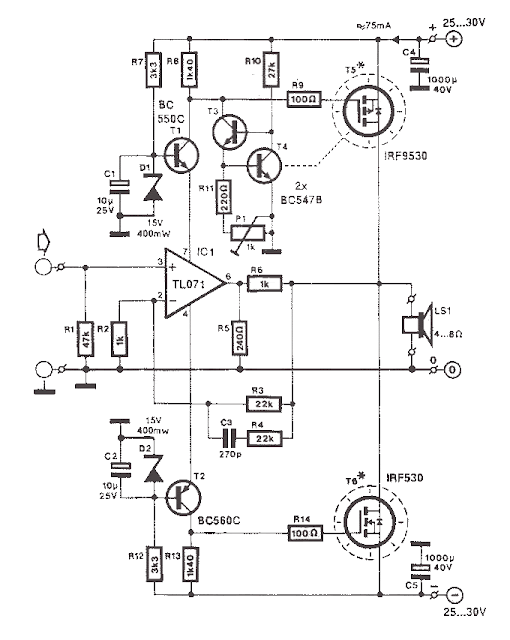
   This simple mosfet power audio amplifier circuit, with TL071 and 2 mosfets (IRF9530, IRF530) power amplifiers can deliver up to 45W on 8 ohm. This schematic is based on Siliconix application and is based on variations of voltage on the 2 resistors serial inserted on the voltage supplier of the operational amplifier driver. The mosfet transistors must be mounted on a heatsink at least 1K/W.  Amplifier efficiency is 70%, distortions at cut frequency were at most 0.2% at 20Hz on 8 ohm and 10W. With a power supply of +/- 30V the mosfet audio amplifier can deliver 45W on 8 ohm and 70w on 4 ohm. Remember that this audio amplifier is not protected on short circuits so every time you switch on check to see if the speaker is connected.

MOSFET Audio Amplifier  Circuit diagram:

TL071 MOSFET Audio Amplifier 1 x 70w

4/28/2015

Subwoofer Amplifier Circuit 30W

 Subwoofer Amplifier Circuit 30W description:

     This circuit with 30w output Power circuit. This Amplifier circuit is very suitable for use in subwoofer amplifier system based on IC SI1030G. Amplifier has 30W output with 8 ohm impedance. Supply voltage required minimum of 12 volts and a maximum of up to 22 volts DC.

 Subwoofer Amplifier Circuit 30W Circuit diagram:

 Subwoofer Amplifier Circuit 30W
 Subwoofer Amplifier Circuit 30W

  Subwoofer Amplifier Circuit 30W Partlist:

R1 = 100K
R2 = 1R
C1 = 2.2uF
C2 = 100uF
C3 = 47uF
C4 = 100nF
C5 = 10uF
C6 = 47uF
C7 = 100uF
IC = SI1020GL , SI1030G

Audio Amplifier 1000W wtih active speaker

Audio Amplifier 1000W description:

I think you've seen or even have an active speaker and there is written 1500 watts PMPO (Peak Music Power Output), make no mistake this is different from Power Amplifier Active Speaker, I often dismantle such Active Speaker in it only a power with power no more than 150 watts by using the transformer 2-3 Ampere. PMPO is not a real power which is issued by the Power Amplifier, but counting all the speakers that there is, for example: if there are 5 pieces of speakers on each channel and each speaker has a power of 10 W then it is 100 W PMPO.

Audio Amplifier 1000W circuit diagram:

Audio Amplifier 1000W

While this 1000 Watt Power Amplifier minimal use transformer 20 Ampere. And the output of Power AmplifierDC voltage contains approximately 63 volts, with currents and voltages of this magnitude, this 1000 Watt Power Amplifier will not hesitate hesitate to destroy your woofer speakers to connect. To overcome that then before the speaker on connects to 1000 Watt Power Amplifier must be in pairs Speaker Protector.
Actually if you want to create a Power Amplifier with great power does not have to make a Power Amplifier with great power. Example: you want to create a Power Amplifier with 10 000 Watt power. You do not have to assemble a Power Amplifier with power of 10,000 watts, but you assemble the power Power Amplifier Small but many, such as you assemble the Power Amplifier with 1000 Watts of power for as many as 10 pieces, it will produce 10 000 Watt Power Amplifier helpless.

Audio Amplifier 1000W parts


    Circuit uses power transistors pair of 5 x 5 x 2SA1216 and 2SC2922 and 2SC1583 use a differential amplifier that actually contains 2 pieces of transistors that are in containers together. Why use such built-in amplifier differental tujuanya so identical / similar, could have uses 2 separate transistors but can result in amplifier so it is not symmetrical.

Stereo Power Amplifier 3000W

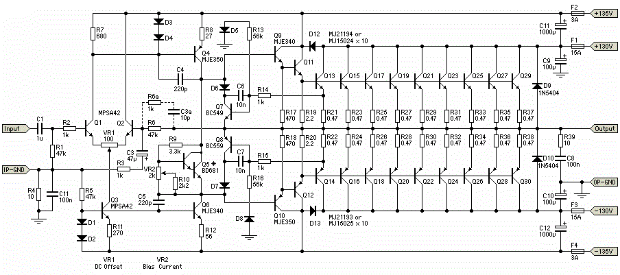
Stereo Power Amplifier 3000W Description

This power amplifier circuit using a transistor amplifier from the front, signal splitter, driver and power amplifier. Current consumption required is quite large power amplifier that is 15-20 A 1500W power amplifier circuits for this. Supply voltage needed by the power of this amplifier is the optimal working order symmetrical 130VDC (130VDC-130VDC ground). 1500W amplifier circuit below is a picture series of mono, stereo if you want to make it necessary to make two copies of the circuit. For more details can be viewed directly image the following 1500W power amplifier circuit. In the above series of power amplifier 1500W is equipped to control a DC Offset function to set the power amplifier is turned on at the moment and with no input signal then the output should be 0VDC. Then also equipped with a flow regulator to the power amplifier bias. Final part of this power amplifier requires adequate cooling to absorb the heat generated. Power amplifier is not equipped with a speaker protector, therefore it is necessary diapsang protector on the speaker output so that when the power amplifier is not the case turned on the beat to the speaker that can damage the speaker. The 1N5404 diodes can withstand a peak non-repetitive current of 200A. Higher rated components may be used if desired. The voltage rating needs to be at least 400V.

Stereo Power Amplifier 3000W crcuit diagram

Stereo Power Amplifier 3000W


TDA1562Q Audio Amplifier 50W

 TDA1562Q general description:

Philips designers have further improved a number of properties of the IC, among which the power output. According to the Philips datasheet, the improved device, the TDA1562Q, can deliver 70 watts into 4 ohms, but that is at the cost of the distortion, which at 10 per cent is rather too high, even for in a car. The prototype of the design described in this article provides 54 watts into 4 ohms at 1 per cent distortion. Since the number of requisite external components is smaller than in the case of the earlier device, the printed-circuit board is even more compact than that for the February 1995 amplifier.


 TDA1562Q features:


  • Low power dissipation during reproduction of music signals
  • Proof against short-circuits
  • Protection against excessive temperatures
  • Standby switch
  • No power-on or power-off clicks
  • Visible error indication
  • Measurement results (at Ub=14.4 V)
  • Supply voltage 8–18 V
  • Sensitivity 760 mV r.m.s.
  • Input impedance 70 kΩ
  • Power output 54 W r.m.s. into 4 Ω (f=1 kHz; THD+N=1%)
  • Harmonic distortion (THD+) at 1 W into 4 Ω: 0.046% (1 kHz)0.29% 20Hz) at 35 W into 4 Ω: 0.12% (1 kHz) 0.7% (20 kHz)
  • Signal-to-noise ratio (with 1 W into 4 Ω) 88 dBA
  • Power bandwidth 7.5 Hz – 185 kHz (at 25 W into 4 Ω)
  • Quiescent current about 135 mA (‘on’)


TDA1562Q applications:


  • Television sets
  • Home-sound sets
  • Multimedia systems
  • All mains fed audio systems
  • Car audio (boosters).

TDA1562Q amplifer diagram:


TDA1562Q pcb:


TDA1562Q part lists:

  • R1= 1MΩ
  • R2 = 4kΩ7
  • R3 = 1kΩ
  • R4 = 100kΩ
  • Capacitors:
  • C1,C2 = 470nF
  • C3,C4 = 10µF 63V radial
  • C5,C6,C8 = 4700µF 25V radial
  • (18mm max. dia., raster 7.5 mm)
  • C7 = 100nF, raster 5 mm
  • Semiconductors:
  • D1 = high-efficiency-LED
  • IC1 = TDA1562Q (Philips)
  • Miscellaneous:
  • S1 = single-pole on/off switch
  • Four spade connectors, PCB mount
  • Heatsink for IC1 (Rth<2.5 K/W)
  • PCB, order code 000004-1 (see Readers Services pages)

TDA7560 Audio Amplifier 4x50W

TDA7560 general description:


TDA7560 is a 4 x 45W QUAD BRIDGE car audio amplifier plus HSD. The TDA7560’s inputs are ground-compatible and can stand very high input signals (± 8Vpk) without any performances degradation. If the standard value for the input capacitors (0.1mF) is adopted, the low frequency cut-off will amount to 16 Hz. The TDA7560 is a breakthrough BCD (Bipolar / CMOS / DMOS) technology class AB Audio Power Amplifierin Flexiwatt 25 package designed for high power car radio. The fully complementary P-Channel/N-Channel output structure allows a rail to rail output voltage swing which, combined with high output current and minimised saturation losses sets new power references in the car-radio field, with unparalleled distortion performances.

TDA7560 features:

  • 4 x 50W/4W MAX.
  • 4 x 45W/4W EIAJ
  • 4 x 30W/4W @ 14.4V, 1KHz, 10%
  • 4 x 80W/2W MAX.
  • 4 x 77W/2W EIAJ
  • 4 x 55W/2W @ 14.4V, 1KHz, 10%
  • EXCELLENT 2W DRIVING CAPABILITY
  • HI-FI CLASS DISTORTION
  • LOW OUTPUT NOISE

TDA7560 amplifier circuit diagram:

TDA7560 Audio Amplifier 4x50W

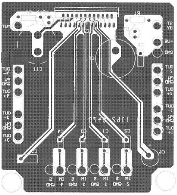
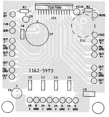
TDA7560 layout:

pcb layout TDA7560 Audio Amplifier 4x50W
pcb layout for TDA7560 Audio Amplifier 4x50W
pcb layout TDA7560 Audio Amplifier 4x50W

4/27/2015

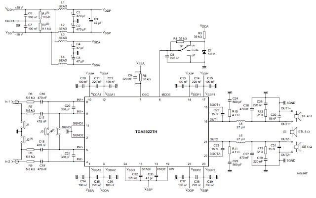
TDA8922 Audio Amplifier 2 x 25W

TDA8922 general description:


The TDA8922 is a high efficiency class-D audio power amplifier with very low dissipation. The typical output power is 2 × 25 W. The device is available in the HSOP24 power package with a small internal heatsink and in the DBS23P through-hole power package. Depending on the supply voltage and load conditions, a very small or even no external heatsink is required. The amplifier operates over a wide supply voltage range from ±12.5 to ±30 V and
consumes a very low quiescent current. TDA8922 Audio Amplifier 2 x 25W


TDA8922 features:
  • High efficiency (∼90%)
  • Operating supply voltage from ±12.5 to ±30 V
  • Very low quiescent current
  • Low distortion
  • Usable as a stereo Single-Ended (SE) amplifier or as a mono amplifier in Bridge-Tied Load (BTL)
  •  Fixed gain of 30 dB in Single-Ended (SE) and 36 dB in Bridge-Tied Load (BTL)
  • High output power
  • Good ripple rejection
  • Internal switching frequency can be overruled by an external clock
  • No switch-on or switch-off plop noise
  • Short-circuit proof across load and to supply lines
  • Electrostatic discharge protection
  • Thermally protected.

TDA8922 aplications:
  • Television sets
  • Home-sound sets
  • Multimedia systems
  • All mains fed audio systems
  • Car audio (boosters).

TDA8922 circuit:


Circuit diagram TDA8922 Audio Amplifier 2 x 25W
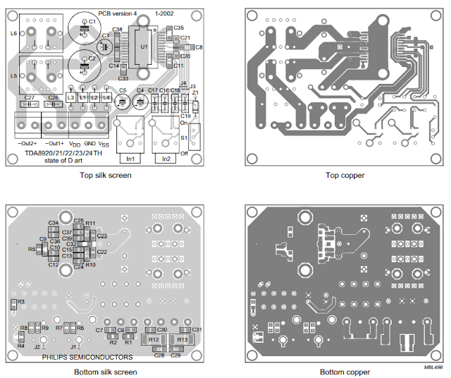
TDA8922 layout and pcb:
pcb layout TDA8922 Audio Amplifier 2 x 25W

TDA8922 datasheet:


TDA7482 Audio Power Amplifier 1-channel 1 x 25W

TDA7482 general description:


The TDA7482 is an audio class-D amplifier assembled in Multiwatt15 package specially designed for high efficiency applications mainly for TV and HomeStereo sets. TDA7482 Audio Amplifier 1 x 25W

TDA7482 features:


  • 25W OUTPUT POWER:
  • RL =8Ω/4Ω; THD = 10%
  • HIGHEFFICIENCY
  • WIDE SUPPLY VOLTAGE RANGE (UP TO±25V)
  • SPLITSUPPLY
  • OVERVOLTAGEPROTECTION
  • ST-BY AND MUTEFEATURES
  • SHORTCIRCUIT PROTECTION
  • THERMALOVERLOADPROTECTION

TDA7482 circuit diagram:

TDA7482 Audio Amplifier 1 x 25W
TDA7482 Audio Amplifier 1 x 25W circuit diagram

TDA7482 sterio circuit layout:

PCB layout TDA7482 Audio Amplifier 1 x 25W
TDA7482 Audio Amplifier 1 x 25W pcb layout

LM386N Audio Power Amplifer Amplifier 1x2W

LM386N general description:


The LM386 is a power amplifier designed for use in low voltage consumer applications. The gain is internally set to 20 to keep external part count low, but the addition of an external resistor and capacitor between pins 1 and 8 will increase the gain to any value up to 200. The inputs are ground referenced while the output is automatically biased to one half the supply voltage. The quiescent power drain is only 24 milliwatts when operating from a 6 volt supply, making the LM386 ideal for battery operation. LM386N Audio Amplifier 1x2W

LM386N features:

  • Battery operation
  • Minimum external parts
  • Wide supply voltage range: 4V–12V or 5V–18V
  • Low quiescent current drain: 4mA
  • Voltage gains from 20 to 200
  • Ground referenced input
  • Self-centering output quiescent voltage
  • Low distortion: 0.2% (AV = 20, VS = 6V, RL = 8Ω, PO =
  • 125mW, f = 1kHz)
  • n Available in 8 pin MSOP package

LM386N circuit diagram:

<h2>LM386N Audio Amplifier 1x2W</h2>
LM386N Audio Amplifier 1x2W

LM386N layout:

LM386N pcb layout
LM386N pcb layout

LM386N pin layout:

LM386N pin layout:
LM386N pin layout:

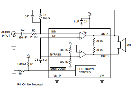
NCP2890 Audio Amplifier 1W

NCP2890 general description:

The NCP2890 is an audio power amplifier designed for portable communication device applications such as mobile phone applications. The NCP2890 is capable of delivering 1.0 W of continuous average power to an 8.0 BTL load from a 5.0 V power supply, and 320 mW to a 4.0 BTL load from a 2.6 V power supply. The NCP2890 provides high quality audio while requiring few external components and minimal power consumption. It features a low−power consumption shutdown mode, which is achieved by driving the SHUTDOWN pin with logic low. The NCP2890 contains circuitry to prevent from “pop and click” noise that would otherwise occur during turn−on and turn−off transitions. For maximum flexibility, the NCP2890 provides an externally controlled gain (with resistors), as well as an externally controlled turn−on time (with the bypass capacitor). Due to its excellent PSRR, it can be directly connected to the battery, saving the use of an LDO. This device is available in a 9−Pin Flip−Chip CSP (standard Tin−Lead and Lead−Free versions) and a Micro8 package. NCP2890 Audio Amplifier 1W

NCP2890 features:

  • 1.0 W to an 8.0  BTL Load from a 5.0 V Power Supply
  • Excellent PSRR: Direct Connection to the Battery
  • “Pop and Click” Noise Protection Circuit
  • Ultra Low Current Shutdown Mode
  • 2.2 V−5.5 V Operation
  • External Gain Configuration Capability
  • External Turn−on Time Configuration Capability
  • Up to 1.0 nF Capacitive Load Driving Capability
  • Thermal Overload Protection Circuitry
  • AEC−Q100 Qualified Part Available
  • Pb−Free Packages are Available
  • NCV Prefix for Automotive and Other Applications Requiring Site and Control Changes

NCP2890 aplications:

  • Portable Electronic Devices
  • PDAs
  • Wireless Phones

NCP2890 circuit diagram: 

NCP2890 Audio Amplifier 1W
Circuit diagram NCP2890 Audio Amplifier 1W

NCP2890 layout pcb: 

PCB layout NCP2890 Audio Amplifier 1W
PCB layout NCP2890 Audio Amplifier 1W

TDA8560Q Audio amplifier 2x40W

TDA8560Q general description:

Unfortunately, some of the proposed scheme in the network and even a scheme recommended by the developer (Philips), fail to achieve the desired result. As an example of how not to suggest that you include the TDA8560 material published on Online Soldering: Car Amplifier 2x40 Watt (I should note that everything except the input circuits and the number of points on diet, still deserves attention). the initial inclusion of IMS (at power up, the load is connected and there is no input signal) can throw you into a state of perplexity / mild shock (it depends on the degree of hope is for your TDA). Chip is unstable, there are noises when the input signal is amplified last weakly and passed with distortions. IC bypass surgery fixed resistor at the input, the other measures in consultation with the source device does not help. Why and what to do? Really caught Palen chip and will have to buy a new one? Not so fast! The fact that Philips did not include measures to prevent the self-excitation of the IC, but I think they know about it, but do not tell anyone (not good, gentlemen!) Rid chip excitement can (and should) in a way that is not described here. This is so far, my little secret. Usually TDA8560 include approximately recommend the following scheme: TDA8560Q Audio amplifier 2x40W

TDA8560Q Features:

  • Supply voltage: 6 - 18; typical 14.4 V.
  • The peak output current: 7.5 A.
  • The current in idle mode: 120 mA.
  • Long-term power output, with
  • RL = 4 ohms, THD = 10%, F = 1 kHz, 25 W,
  • RL = 2 ohms, THD = 10%, F = 1kHz: 40W.
  • Voltage gain, Au: 40 dB.
  • Input Impedance: 30 ohms.
  • Input Sensitivity: 100 mV.
  • Frequency response: 20 - 20000 Hz.
  • Requires very few external components
  • High output power
  • Low output offset voltage
  • Fixed gain
  • Diagnostic facility (distortion, short-circuit and temperature detection)
  • Good ripple rejection
  • Mode select switch (operating, mute and standby)
  • Load dump protection
  • Short-circuit safe to ground, to VP and across the load
  • Low power dissipation in any short-circuit condition
  • Thermally protected
  • Reverse polarity safe
  • Electrostatic discharge protection
  • No switch-on/switch-off plop
  • Flexible leads
  • Low thermal resistance.

TDA8560Q amplifier diagram, circuit:

TDA8560Q amplifier diagram, circuit

TDA8560Q layout:

TDA8560Q amplifier Layout

TDA8560Q amplifier pcb

Datasheet for TDA8560Q: Download

4/10/2015

Tunable bandpass filters variable resistors


Tunable bandpass filters variable resistors


One of the difficulties in the design of higher-order tunable bandpass filters is achieving correct tracking of the variable resistors in the RC networks. The use of switched capacitor networks can obviate that difficulty, as is shown in this filter. The filter can be divided roughly into two stages: an oscillator that controls the electronic switches arid the four phase-shift networks that provide the filtering proper. The oscillator, based on a 555, generates a pulsating signal whose frequency is adjustable over a wide range: the duty factor varies from 1:10 to 100:1. Electronic switches ESI through ES4 form the variable resistors whose value is dependent on the frequency of the digital signal. The operation of these switches is fairly simple. When they are closed, their resistance is about 60 ; when they are open, it is virtually infinitely high. a switch is closed for, say, 25% of the time, its average resistance is therefore 240 . `Varying the open:closed ratio of each switch varies the equivalent average resistance. The switching rate of the switches must be much greater than the highest audio frequency to prevent audible interference between the audio and the clock signals. The input signal causes a given direct voltage across CI, so the op amp can be operated in a quasisym-metric manner, in spite of the single supply voltage. The direct voltage is removed from the output signal by capacitor C10. The fourth-order filter in the diagram can be used over the entire audio range and it has an amplification of about 40, although this depends to some extent on the clock frequency. The bandwidth depends mainly on the set frequency. The circuit draws a current of not more than 15 mA.
Tunable bandpass filters variable resistors

Stereo Amplifier Circuit TDA2007A 12W Bridge


Stereo Amplifier Circuit TDA2007A 12W Bridge general description


The following schematic shows 12 W Bridge Amplifier circuit diagram as an application of the TDA2007A a class AB dual audio power amplifier which is designed for stereo application in music centers, TV receivers and portable radios. According to the datasheet, this TDA2007A has features such high output power, high current capability, AC short circuit protection, and thermal overload protection.
For description about stereo test circuit, PCB components layout of the circuit, the recommended values of the components of Stereo 12W Bridge Amplifier Circuit Diagram using TDA2007A can be seen.
 Stereo Amplifier Circuit TDA2007A 12W Bridge circuit diagram
 Stereo Amplifier Circuit TDA2007A 12W Bridge
 Stereo Amplifier Circuit TDA2007A 12W Bridge

4/08/2015

Peamp circuit extra-deep bass change capacitor

Peamp circuit extra-deep bass change capacitor

The input impedance is the value of potentiometer Rl. If your instrument has extra-deep bass, change capacitor Cl to 0.5 mF. What appears to be an extra part in the feedback loop is a brightening tone control. The basic feedback from the op amp's output (pin 6) to the inverting input (pin 2) consists of resistor R7, and the series connection of resistor R4 and capacitor C3, which produce a voltage gain of almost 5 (almost 14 dB). That should be more extra oomph than usually needed.
Peamp circuit extra-deep bass change capacitor

Stereo amplifier uses a National LM3871C


Stereo amplifier uses a National LM3871C

Stereo amplifier uses a National LM3871C. The pin numbers in parentheses are for one channel, and those not in parentheses are for the other channel. The supply voltage can be +9 to +30 Vdc at about 10 mA. The output voltage swing is about Vee-2 V pk-pk.
Stereo amplifier uses a National LM3871C

4/07/2015

60W Bass Control Audio Power Amplifier Circuit diagram


Audio Power 60W Bass Control  Amplifier Circuit diagram 

60W Bass Control Audio Power Amplifier Circuit diagram


Audio Power 60W Bass Control  Amplifier Circuit description
This design adopts a well established circuit topology for the power amplifier, using a single-rail supply of about 60V and capacitor-coupling for the speaker(s). The advantages for a guitar amplifier are the very simple circuitry, even for comparatively high power outputs, and a certain built-in degree of loudspeaker protection, due to capacitor C8, preventing the voltage supply to be conveyed into loudspeakers in case of output transistors' failure.
The preamp is powered by the same 60V rails as the power amplifier, allowing to implement a two-transistors gain-block capable of delivering about 20V RMS output. This provides a very high input overload capability.

Audio Power 60W Bass Control  Amplifier Circuit Technical data:
Sensitivity:
70mV input for 40W 8 Ohm output
63mV input for 60W 4 Ohm output
Frequency response:
50Hz to 20KHz -0.5dB; -1.5dB @ 40Hz; -3.5dB @ 30Hz
Total harmonic distortion @ 1KHz and 8 Ohm load:
Below 0.1% up to 10W; 0.2% @ 30W
Total harmonic distortion @ 10KHz and 8 Ohm load:
Below 0.15% up to 10W; 0.3% @ 30W
Total harmonic distortion @ 1KHz and 4 Ohm load:
Below 0.18% up to 10W; 0.4% @ 60W
Total harmonic distortion @ 10KHz and 4 Ohm load:
Below 0.3% up to 10W; 0.6% @ 60W
Bass control:
Fully clockwise = +13.7dB @ 100Hz; -23dB @ 10KHz
Center position = -4.5dB @ 100Hz
Fully counterclockwise = -12.5dB @ 100Hz; +0.7dB @ 1KHz and 10KHz
Low-cut switch:
-1.5dB @ 300Hz; -2.5dB @ 200Hz; -4.4dB @ 100Hz; -10dB @ 50Hz

Notes:
The value listed for C8 is the minimum suggested value. A 3300µF capacitor or two 2200µF capacitors wired in parallel would be a better choice.
The Darlington transistor types listed could be too oversized for such a design. You can substitute them with MJ11014 (Q3) and MJ11013 (Q4) or TIP142 (Q3) and TIP147 (Q4).
T1 transformer can be also a 24 + 24V or 25 + 25V type (i.e. 48V or 50V center tapped). Obviously, the center-tap must be left unconnected.
SW1 switch inserts the Low-cut feature when open.
In all cases where Darlington transistors are used as the output devices it is essential that the sensing transistor (Q2) should be in as close thermal contact with the output transistors as possible. Therefore a TO126-case transistor type was chosen for easy bolting on the heatsink, very close to the output pair.
R9 must be trimmed in order to measure about half the voltage supply from the positive lead of C7 and ground. A better setting can be done using an oscilloscope, in order to obtain a symmetrical clipping of the output waveform at maximum output power.
To set quiescent current, remove temporarily the Fuse F1 and insert the probes of an Avo-meter in the two leads of the fuse holder.
Set the volume control to the minimum and Trimmer R3 to its minimum resistance.
Power-on the circuit and adjust R3 to read a current drawing of about 30 to 35mA.
Wait about 15 minutes, watch if the current is varying and readjust if necessary.

Search This Blog

Blog Archive

Powered by Blogger.

200W Audio Amplifier Circuit

Circuit description: Connecting two TDA2030 thru cheap power transistors we can create a amplifier wich can deliver a higher power. Wi...

Labels

Amplifier Circuits (107) 4 Ω (85) TDA Amplifiers (66) Amplifier (50) 8 Ω (46) Circuit (37) subwoofer (31) Layout (26) audio (26) Subwoofer circuit (25) 2 Ω (23) Class D (23) Subwoofer Amplifier (23) Description (22) PCB (21) Subwoofer Diagram (21) Audio Amplifier (20) Stereo Amplifier (18) 20W (17) Auto Subwoofer (17) Stereo Amp (16) car subwoofer (16) BTL amplifier (14) ClassAB (14) Software (14) Electronic software (13) Sound System (13) 2x10W (12) 4-channel (12) 60W (12) BTL audio amplifier (12) Car Audio (12) Operational Amplifier (12) Power Amplifier (12) 2x12W (10) Audio Power Amplifier (10) Car Stereo (10) 2x25W (9) 5W (9) Car Amplifier (9) Circuit Diagram (9) Dual channel (9) Filter Circuits (9) Speakers (9) 2x40W (8) 2x6W (8) 3W (8) 4x50W (8) Audio Power Amp (8) Class B (8) Guitar Amplifier (8) 10W (7) 2x22W (7) 4x35W (7) 50W (7) Car Stereos (7) Subwoofer car (7) car radio amplifier (7) mono amplifier (7) 100W (6) 12W (6) 1W (6) 2-channel (6) 22W (6) 2w (6) 2x20W (6) 2x30W (6) Features (6) Guitar circuits (6) Microphone (6) Mixer (6) Stereo Preamp (6) general description (6) quad bridge (6) tone control (6) 100W Audio Amplifier (5) 18W (5) 40W (5) 4W (5) 4x45W (5) 6 Ω (5) 70W (5) Amps (5) Audio Processor (5) Car radio (5) Diagram (5) MOSFET (5) Preamplifier (5) applications (5) hi-fi audio power amplifier (5) newamps (5) 15W (4) 2-channel Amplifier (4) 200W (4) 2x100W (4) 2x15W (4) 6W (4) 8W (4) Amplifier High-Performance (4) BTL stereo (4) Bridge Amplifer (4) Class T (4) Datasheet (4) Dual Preamplifier (4) Equalizer circuit (4) Quad power amplifier (4) STK Amplifier (4) Sound Amplifier Circuit (4) Volume Control (4) car radio power amplifier (4) stereo BTL (4) 100W Subwoofer (3) 24W (3) 2x200W (3) 2x50W (3) 3 Ω (3) 3-channel (3) 300W (3) 35W (3) 4-ch amplifier circuit diagram (3) 400W (3) 4x11W (3) 4x12W (3) 4x22W (3) 4x40W (3) 500W (3) 80W (3) AM/FM Tuner (3) Amp (3) Amplifer (3) Arduino (3) Audio Circuit Diagram (3) Audio Speakers (3) Audio signal processing (3) Car Speakers (3) DMOS (3) Digital Audio Amplifier (3) Dual Audio (3) Dual BTL (3) Graphic Equalizer (3) Guitar (3) Guitar Effect Circuit (3) Hi-Fi audio (3) LED (3) Low noise (3) Power Supply (3) STK412-000 (3) Stereo balance meter (3) Subwoofer Design (3) Surround (3) TDA (3) TDA1566 (3) TDA2008 (3) TDA8586 (3) Tips To Save Energy (3) digital controlled (3) guitars (3) single channel (3) stereo headphone (3) 100+100W (2) 1000W (2) 1000W Amplifier (2) 100W Subwoofer Amplifier Circuit (2) 14W (2) 180W + 180W (2) 1ch BTL Power Amplifier (2) 2 x 210 Watt (2) 200W amplifier (2) 25W (2) 28w (2) 2x110W (2) 2x11W (2) 2x120W (2) 2x150W (2) 2x1W (2) 2x210W (2) 2x24W (2) 2x300W (2) 2x35W (2) 2x46W (2) 2x5W (2) 2x7W (2) 2x80W (2) 3 channel amplifier (2) 30W (2) 30w Amplifier (2) 32 Ω (2) 32W (2) 45W (2) 4x13W (2) 4x25W (2) 4x30 (2) 4x6W (2) 4x70W (2) 5 Band Graphic Equalizer Circuit (2) 92W (2) AM receiver (2) AM/FM Radio (2) AN12941A (2) AN12972A (2) AN7110 (2) AN7163 (2) AN7177 (2) AN7531SA (2) ARM (2) ARM Microcontroller (2) Aliexpress circuits (2) Amplifier Transistors (2) Audio Filter Circuits (2) Audio Mixer (2) Audio Mixer Circuit (2) Audio Preamplifier (2) BCDMOS technology (2) BTL power amplifier (2) CMOS (2) Car Subwoofers (2) Ceiling Speakers (2) Class H (2) Equalizer (2) FM Stereo (2) FM Transmitter (2) Guitar Amps (2) Guitar circuit (2) HA13116 (2) Hi-Fi systems (2) IRF530 (2) IRF9530 (2) LA4460N (2) LM1875 (2) LM380 (2) LM3886 (2) LPC2124 (2) MOSFET Audio Amplifier (2) Microcontroller (2) Music System (2) NE5532 (2) NE555 (2) Peak Indicator (2) Power Amp (2) Recording (2) STA501 (2) STEREO (2) STK400-530 (2) Sound (2) Sound Decoder (2) Speaker (2) Stereo Decoder (2) Stereo Headphone Amplifier (2) TA8210AH Amplifier (2) TDA1015 (2) TDA1037 (2) TDA1083 (2) TDA1514A (2) TDA1517 (2) TDA1562Q (2) TDA1904 (2) TDA1905 (2) TDA1910 (2) TDA2003 (2) TDA2004 (2) TDA2051 (2) TDA2613 (2) TDA7056 (2) TDA7264 (2) TDA7269 (2) TDA7294 (2) TDA7298 (2) TDA7299 (2) TDA7334 (2) TDA7360 (2) TDA7454 (2) TDA7481 (2) TDA7490 (2) TDA7511 (2) TDA7850 (2) TDA8562Q (2) TDA8922 (2) TDA8924 (2) TDA8929T (2) TDA8931 (2) Two-channel Amplifier (2) best car speakers (2) demodulators FM (2) high performance hi-fi amplifier (2) partlist (2) quad bridge car radio amplifier (2) speaker protection (2) stereo car radio power amplifier (2) stereo tv (2) subwoofer circuit diagram (2) subwoofer for car (2) subwoofer preamp circuit diagram (2) subwoofers for cars (2) /Playback Pre-/Power Amplifier (1) 0.5W (1) 1 Ω (1) 1-channel (1) 1.2W (1) 1.6W (1) 10+10+10W (1) 1000 watts power amplifier schematic diagram (1) 1000W MOSFET (1) 100W Guitar Amplifier (1) 100W MOSFET (1) 10W circuit (1) 10W+10W (1) 1100W (1) 12 W car radio power amplifier (1) 1200W (1) 120W (1) 13.5W (1) 130W (1) 140 watt subwoofer (1) 140W (1) 14W+2x7.5W (1) 150 Amplifier (1) 150W (1) 150W+150W+150W (1) 170W amplifier (1) 17W (1) 18W Class-B Audio Amplifier (1) 19V (1) 1Kw Amplifier (1) 2 × 13 W (1) 2.1 channel (1) 2.7W (1) 200 Watts Amplifier Circuit (1) 200 watt mosfet amplifier circuit (1) 200W Audio Amplifier Circuit Diagram (1) 200W amplifier circuit (1) 200w stereo digital audio power amplifier (1) 20W+20W (1) 20W+20W+20W (1) 21W (1) 240W (1) 26 W BTL (1) 26V (1) 27W (1) 2SK1066 (1) 2x1.4W (1) 2x1.7W (1) 2x1100W (1) 2x13W+26W (1) 2x14W (1) 2x170W (1) 2x175W (1) 2x18W (1) 2x2.2W (1) 2x23W (1) 2x250W (1) 2x2W (1) 2x32W (1) 2x45W (1) 2x5.5W (1) 2x500W (1) 2x60W (1) 2x60mW (1) 2x7.3W (1) 2x70W (1) 2x75mW (1) 3 band equalizer guitar (1) 3-channel mixer (1) 30 Watt x 5 (1) 300W Subwoofer (1) 300W Subwoofer Power Amplifier (1) 315W (1) 32W Stereo (1) 350 watt mono amplifier (1) 35mW (1) 3x10W (1) 3x150W (1) 3x20W (1) 3x90Watt (1) 4 channel amplifier (1) 4 channel audio amplifier circuit diagram (1) 4 channel car amplifier circuit (1) 4 × 13 W (1) 4-Channel Outputs Volume Tone Balance (1) 4.4W (1) 4.5W (1) 400W IRFP448 (1) 40W Amplifier (1) 430mW (1) 43W (1) 4461N (1) 44W (1) 47W (1) 4x100W (1) 4x15W (1) 4x20W (1) 4x30W (1) 4x33W (1) 4x34W (1) 4x37W (1) 4x38W (1) 4x42W (1) 4x43W (1) 4x44W (1) 4x46W (1) 4x47W (1) 4x6.5W (1) 4x60W (1) 4x75W (1) 4x7W (1) 4Ω (1) 5 channel amplifer (1) 5-band stereo (1) 5.1 subwoofer circuit diagram (1) 5.4W (1) 5.5W (1) 5.8W (1) 55 dB (1) 56W (1) 5W+5W (1) 60 Watt (1) 60W Hi-Fi Power Amplifier Circuit (1) 60W+60W (1) 6x30W (1) 7 segment display Arduino (1) 7.5W (1) 70 Watt MOSFET Audio Power Amplifier (1) 70V (1) 75W (1) 7W (1) 80W Subwoofer (1) AA (1) AAA (1) AC and DC (1) AD1991 (1) AD199x (1) ADC (1) ADDR (1) ALC circuit (1) AM Radio Circuits (1) AM Tuner (1) AM tuner RF amplifier (1) AM-demodulator (1) AM/FM (1) AN17000A (1) AN17810 (1) AN17813A (1) AN17831A (1) AN17850A (1) AN4250 (1) AN4558 (1) AN5275 (1) AN5277 (1) AN5279 (1) AN7060 (1) AN7086S (1) AN7112 (1) AN7116 (1) AN7124 (1) AN7125 (1) AN7131 (1) AN7134 (1) AN7147 (1) AN7148 (1) AN7158N (1) AN7161 (1) AN7164 (1) AN7170 (1) AN7176 (1) AN7176K (1) AN7190 (1) AN7190NK (1) AN7195 (1) AN7198 (1) AN7208SA (1) AN7273 (1) AN7310N (1) AN7337N (1) AN7500FHQ (1) AN7504SB (1) AN7510 (1) AN7511 (1) AN7512 (1) AN7515SH (1) AN7516SH (1) AN7551Z (1) AN7555NZ (1) AN7560 (1) AN7561Z (1) AP130 (1) AP4809 (1) APA2065 (1) Altium Designer (1) Am Radio (1) Amplifier Circuit diagram (1) Amplifier Circuit for TV (1) Amplifier Features (1) Amplifier circuit (1) Amplifiers circuits (1) Arduino Uno Rev3 schematic (1) Audio Car (1) Audio Codec (1) Audio Equalizer (1) Audio IC (1) Audio Power Circuit LM Amplifiers (1) Audio Procesor (1) Audio Systems (1) Auto Radio (1) Auto Reverse (1) BA10324A (1) BA10324AF (1) BA10324AFV (1) BA1442A (1) BA328 (1) BA3306 (1) BA3430S (1) BA3826S (1) BA3837 (1) BA3840KV (1) BA3842 (1) BA3853 (1) BA3870 (1) BA3880 (1) BA5204 (1) BA5210FS (1) BA5406 (1) BC 547B (1) BCD technology (1) BICMOS (1) BTL car audio (1) BTL/SE (1) BTSC (1) BUZ23 (1) Basic Low Power AM transmitter (1) Bass (1) Bass Amplifier (1) Bass Boost System (1) Bass Guitar (1) Battery Level Indicator (1) Bridge-Tied Load (1) Build A Subwoofer Box (1) Building subwoofer (1) CS44130 (1) Cable Set-Top Products (1) Car Subwoofer Amplifier Circuit Diagram (1) Car audio amplifier with IC TA7203P (1) Center-Channel (1) Circuit Mixer (1) Circuit Simulator (1) Class T amplifiers (1) Class-B (1) Class-D (1) Clipping Detector (1) Computer Speaker (1) DDD (1) DDX-2060 (1) DIL (1) DMOS Audio Amplifier (1) DTL (1) DVCs (1) DVD Receivers (1) Denon Subwoofers (1) Design a Subwoofer Box (1) DesignSpark PCB (1) Detector (1) Diagram mixer (1) Diference Amplifier (1) Differentiator (1) Digital Delay (1) Digital Echo (1) Digital Radio (1) Digital TV (1) DipTrace (1) Dual Audioprocessor (1) Dual Pre Amplifier (1) Dual amplifier (1) Dual operational amplifier (1) Dynamic Distortion Detector (1) EDWinXP (1) EUA5202 (1) Eagle (1) Easy to Make (1) Electric Motor (1) Electricity (1) Electronic Componets (1) Equalized-preamp (1) ExpressPCB (1) FET (1) FM demodulator (1) FM processing (1) FM radio (1) FM radio Receivers (1) FM receivers (1) FM sound (1) FM stereo decoder (1) FM tuners (1) FOUR CHANNEL (1) FreePCB (1) Guitar Amp Circuit (1) Guitar Amplifier Circuit (1) Guitar pre-amplifier (1) Guitar vocal adaptor amp (1) HA12002 (1) HA13117 (1) HA13118 (1) HA13119 (1) HA13127 (1) HA13150A (1) HA13151 (1) HA13153 (1) HA13155 (1) HA13156 (1) HA13158A (1) HA13159 (1) HA1397 (1) HDMI (1) HEXFET (1) Headphone (1) High Gain (1) High Signal-to-Noise ratio (1) How to Build a Subwoofer Box (1) How to Match a Car Subwoofer (1) I2C Bus Interface (1) IF Amplifier (1) IF-PLL (1) IF-PLL demodulator (1) IRFP260 (1) ISS filter (1) Integrator (1) Inverting (1) It begins with your commitment (1) KA22134 (1) Kicad (1) LA3160 (1) LA4440 (1) LA4445 (1) LA4446 (1) LA4500 (1) LA4558 (1) LA4625 (1) LA4628 (1) LA4725 (1) LM Series (1) LM101 (1) LM101A (1) LM12 (1) LM2002 (1) LM2005 (1) LM378 (1) LM383 (1) LM383A (1) LM386 (1) LM386N (1) LM3876 (1) LM391 (1) LM4732 (1) LM4766 (1) LM4851 (1) LM567 Infrared Transmitter Circuit (1) LM6161 (1) LM6261 (1) LM6361 (1) LM833 (1) LS404 (1) LX1720 (1) Line Level Stereo (1) Loudspeaker (1) Low Noise Amplifier (1) Low distortion (1) M65831A (1) MC1350 (1) MJE340 (1) MJE350 (1) MOSFET power amplifier (1) MOSFET quad bridge (1) Microphone System (1) Mini Portable Guitar Amplifier (1) Mitsubishi M5226P (1) Mobile Car Stereo Amplifier (1) Modulated Receiver (1) Mp3 Player (1) Mtx Audio (1) Multi-channel (1) NCP2890 (1) NE 5532 (1) NTE1285 (1) NTE1371 (1) NTE1373 (1) NTE7011 (1) NTE7059 (1) Noise Transistor (1) Offset (1) Overload (1) P-CAD (1) PA03 (1) PA03A (1) PA05 (1) PCB mixer (1) PLL Stereo (1) PLL synthesizer (1) PNP-NPN (1) PWM processor (1) Peamp circuit (1) Phase Locked Loop (PLL) (1) Phono/line adapter (1) Power (1) Power Audio (1) Power Comparator (1) Power Stage Amplifier (1) Preamp Circuit (1) Proteus (1) Pulse Generator (1) Pulse-Frequency (1) Quad Half-Bridge (1) Quad Operational Amplifier (1) RDA Demodulator (1) RDS (1) RDS Filter (1) RF (1) Radio Players (1) Remote amplifier dsp (1) SA58631 (1) SA58632 (1) SA58672 (1) SAP Decoder (1) SAVING ENERGY (1) SCART channel (1) SEPP (1) SMA428A (1) ST-BY (1) STA001 (1) STA323W (1) STA502 (1) STA5100 (1) STA515 (1) STA5150 (1) STA516B (1) STA517B (1) STA7056 (1) STA7575 (1) STK442-130 (1) STK084 (1) STK086G (1) STK400-030 (1) STK4017 (1) STK4044 (1) STK4048 (1) STK4050 (1) STK4050V (1) STK413-000 (1) STK4221 (1) STK433-330 (1) STK433-330N-E (1) STK443-090 (1) STK465 (1) Signal (1) Single Channel Amplifier (1) Six-Channel (1) Sofware (1) Sound Control (1) Sound Demodulator (1) Sound Processor (1) Spectrum Analyzer (1) Sprint-Layout (1) Stand-by options (1) Stereo 300W Audio Amplifier (1) Stereo Audio Amplifier System (1) Stereo Car Audio Amplifie (1) Stereo Demodulator (1) Stereo Digital (1) Stereo Inputs (1) Stereo Radio Circuit (1) Stereo System (1) Stereo System Ic (1) Stereo applications (1) Stereo balance tester (1) Stereo modulator (1) Stereo stk013 audio amplifier circuit (1) Subwoofer 400W (1) Subwoofer output (1) Summing (1) Surround Sound Matrix (1) TA Series (1) TA0102A (1) TA0103A (1) TA0105A (1) TA2022 (1) TA2024C (1) TA3020 (1) TA8159FN (1) TA8220H (1) TA8225H (1) TA8233H (1) TA8238K (1) TA8246AH (1) TA8251AH (1) TA8255AH (1) TA8260 (1) TA8263 (1) TA8273 (1) TA8276H (1) TA8277 (1) TAA4100 (1) TAS5122 (1) TAS5132 (1) TB2903HQ (1) TDA 1524A (1) TDA Amplifier Circuit (1) TDA1001B (1) TDA1010A (1) TDA1011 (1) TDA1013B (1) TDA1016 (1) TDA1020 (1) TDA1308 (1) TDA1400 (1) TDA1510 (1) TDA1512 (1) TDA1515 (1) TDA1516 (1) TDA1518 (1) TDA1519 (1) TDA1520A (1) TDA1521 (1) TDA1523 (1) TDA1524 (1) TDA1526 (1) TDA1552Q (1) TDA1554Q (1) TDA1555Q (1) TDA1556Q (1) TDA1557Q (1) TDA1558Q (1) TDA1560Q (1) TDA1561Q (1) TDA1563Q (1) TDA1564 (1) TDA1565 (1) TDA1572 (1) TDA1599 (1) TDA1908 (1) TDA2002 (1) TDA2005 (1) TDA2006 (1) TDA2007 (1) TDA2009A (1) TDA2020 (1) TDA2025 (1) TDA2030 (1) TDA2040 (1) TDA2050 (1) TDA2052 (1) TDA2075 (1) TDA2075A (1) TDA2320A (1) TDA2500 (1) TDA2611 (1) TDA2611A (1) TDA2614 (1) TDA2615 (1) TDA2616 (1) TDA2822 (1) TDA3803 (1) TDA7050T (1) TDA7052 (1) TDA7231A (1) TDA7245 (1) TDA7250 (1) TDA7253 (1) TDA7256 (1) TDA7261 (1) TDA7262 (1) TDA7263 (1) TDA7263M (1) TDA7266 (1) TDA7266B (1) TDA7267 (1) TDA7268 (1) TDA7269A (1) TDA7293 (1) TDA7295 (1) TDA7296 (1) TDA7296A (1) TDA7297 (1) TDA7310 (1) TDA7313 (1) TDA7317 (1) TDA7318 (1) TDA7319 (1) TDA7330B (1) TDA7332 (1) TDA7336 (1) TDA7338 (1) TDA7339 (1) TDA7348 (1) TDA7350 (1) TDA7365 (1) TDA7370 (1) TDA7374 (1) TDA7374B (1) TDA7375 (1) TDA7376B (1) TDA7377 (1) TDA7381 (1) TDA7382 (1) TDA7383 (1) TDA7384A (1) TDA7385 (1) TDA7388 (1) TDA7391 (1) TDA7393 (1) TDA7394 (1) TDA7396 (1) TDA7430 (1) TDA7433 (1) TDA7443 (1) TDA7451 (1) TDA7462D (1) TDA7468 (1) TDA7469 (1) TDA7476 (1) TDA7480 (1) TDA7482 (1) TDA7494 (1) TDA7495 (1) TDA7496 (1) TDA7497 (1) TDA7497S (1) TDA7499 (1) TDA7502 (1) TDA7560 (1) TDA7561 (1) TDA7562 (1) TDA7563 (1) TDA7563B (1) TDA7564 (1) TDA7564B (1) TDA7565 (1) TDA7566 (1) TDA7567 (1) TDA7572 (1) TDA7575 (1) TDA7594 (1) TDA8426 (1) TDA8496 (1) TDA8510J (1) TDA8511J (1) TDA8512J (1) TDA8542 (1) TDA8543 (1) TDA8547 (1) TDA8551 (1) TDA8552T (1) TDA8552TS (1) TDA8559T (1) TDA8560Q (1) TDA8561Q (1) TDA8563AQ (1) TDA8564Q (1) TDA8565Q (1) TDA8566 (1) TDA8566TH1 (1) TDA8568Q (1) TDA8569Q (1) TDA8571J (1) TDA8576 (1) TDA8580 (1) TDA8581 (1) TDA8588J (1) TDA8591 TDA8591J (1) TDA8593J (1) TDA8594 (1) TDA8595 (1) TDA8596 (1) TDA8851 (1) TDA8920 (1) TDA8925 (1) TDA8926J (1) TDA8927 (1) TDA8927/TDA8929 (1) TDA8928 (1) TDA8932 (1) TDA8932B (1) TDA8943 (1) TDA8944 (1) TDA8946 (1) TDA8947J (1) TDA8950 (1) TDA8954 (1) TDA9610H (1) TDA9821 (1) TDA9830 (1) TDA9847 (1) TDA9852 (1) TDA9853H (1) TDA9861 (1) TDA9873 (1) TDA9874 (1) TDA9875 (1) TDA9880 (1) TDA9887 (1) TDB7910 (1) TEA6360 (1) TL071 (1) TL072 (1) TMPA401DM (1) TOP 10 (1) TP2350B (1) TPA2000D2 (1) TPA3122D2 (1) TTL (1) TV (1) TV application (1) TV sound processor (1) TV/FM (1) Telephone Headphone (1) Thermal Shutdown (1) Thermal protector (1) Tone Control Circuit (1) Tone Controls (1) Tone-Control (1) TopoR (1) Triple Amplifier (1) Tunable bandpass filters variable resistors (1) UART (1) UPC1230H2 (1) USB Powered Stereo (1) VCRs (1) VTR (1) VU Level (1) VU meter (1) Vocal Fader (1) Voice Canceller (1) Voltage (1) Voltage Converter (1) Wire (1) Wireless (1) Wireless am microphone (1) acoustic guitar (1) amplifier for headphone (1) audio HDMI interface (1) audio panoramic interface (1) audio power amplifier ic (1) ba526 (1) band-pass (1) bass boost amplifiers (1) battery (1) cheap guitar amps (1) circuit Schematic (1) computer speakers (1) decoder Circuit (1) demodulators AM (1) diagnostic facility (1) effects loop guitar (1) electric guitar (1) electronic project (1) fault protection (1) filter-free class-D (1) gibson guitars (1) guitar amp amazon (1) guitar amp marshall (1) guitar amp reviews (1) guitar amplifier olx (1) guitar amplifier price (1) guitar amps brands (1) guitar ams (1) guitar parts (1) guitar tube amps (1) ha13128 (1) headphone amplifier circuit using op-amp (1) high-performance (1) home audio amplifier (1) ic (1) lights upon detection (1) lm4702 bridge amplifier (1) lm4702 datasheet (1) lm4702 equivalent (1) lm4702 mosfet amplifier (1) lm4702 pcb (1) lm4702 price (1) lm4702 replacement (1) load detection (1) low pass subwoofer circuit diagram (1) low voltage (1) magnet (1) mono BTL amplifier (1) mono bridge amplifier (1) mosfet amplifier circuit for subwoofer (1) mosfet power amplifier circuit (1) muting (1) new amp (1) nte1165 (1) ohmmeter arduino (1) outdoor speakers (1) pc speakers (1) playback (1) po (1) power amplifier with distortion detector (1) power guitar amplifier (1) preamp gain guitar (1) satellite (1) simple headphone amplifier circuit (1) single-in-line (1) sound decoder circuit (1) speaker stands (1) stereo 175 watt amplifier (1) stereo VU meter (1) stereo headphone amplifier circuit (1) stereo indicator (1) stereo power meter (1) stereo tone control (1) stereo tube amplifier (1) subwoofer circuit diagram pdf (1) subwoofer design software (1) subwoofer filter board (1) subwoofer filter circuit diagram (1) subwoofer filter circuit for tda7294 (1) subwoofer filter circuit using lm324 (1) subwoofer filter circuit using op-amp tl072 (1) subwoofer filter kit (1) subwoofer filter subwoofer filter circuit using lm324 (1) subwoofers and amplifiers (1) symmetrical power supply (1) tda2030 circuit (1) tda2030 ic (1) tda2030 pdf (1) tda2030 pin configuration (1) tda2030 pinout (1) tda2030 power supply (1) tda2030 price (1) tda2030 subwoofer amplifier circuit (1) tda7265 amp circuit (1) tda7265 amplifier circuit (1) tda7265 equivalent (1) tda7265 pcb layout (1) tda7265 power supply (1) tda7265 single supply (1) tda7265 subwoofer circuit diagram (1) tda7265 voltage (1) tda8946j equivalent (1) tda8947j circuit diagram (1) tda8947j equivalent (1) tda8947j pinout (1) tda8947j price (1) tda8947j schematic (1) two-channel audio amplifier (1) uPC1032H (1) uPC1188H (1) voltage regulator (1)