
Telephone AmplifierLF351 and TBA820M


Amplifier description:

This circuit TDA820M Mini Amplifier 2W+2W. Supply Volt 12V, Easy to build and Low cost. If you want mini amplifier circuit , as a result do not be defeated certainly. The sound will a little 2W+2W just but enough with 6 sizes are inch 8ohm loudspeakers. as a result still have a voice good loud the moderately. Request friends have fun the circuit amplifies this miniature please yes.
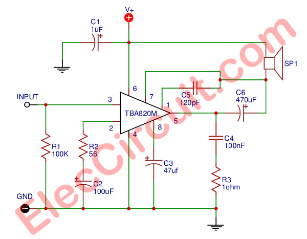
Circuit diagram:


PCB layout:


In Mono style a few parts and very cheap!
TBA820 mini AUDIO AMPLIFIER 1.2W
Here is Circuit Mini power amplifier low watt (1.2W Only). IN circuit have IC TBA820,it old IC Audio amp.


   If phone your light exceedingly ring. Invite come to this way. I thinks this circuit can help. It is Telephone Amplifier circuit. By have pillar equipment be IC LF351 perform enlarge telephone signal from pick up give the power goes up. Before transmit to IC TBA820M for amplify with a loudspeaker next sir. And VR1 perform fine the loud sound or the silent is extremely fond of something. See circuit detail enhances in a picture.


Comments

Popular posts from this blog

One Chip AM/FM Radio with Audio Power Amplifier

Description: The integrated circuit TDA1083 includes, with exception  of the FM front end, a complete AM-/FM-radio-circuit  with audio power amplifier. An internal Z-diode  stabilizes the supply voltage at VS 13 V, which allows  with the aid of a resistor and a rectifier, the circuit to be  driven by a higher external supply voltage. Features: Large supply voltage range VS = 3 to 12 V High AM-Sensitivity Limiting threshold voltage Vi = 50 V Audio output power P0 = 0.7 W AFC-connection for VHF-tuner AM-FM switching without high frequency voltages Applications: AM-/FM- and audio-amplifier Circuit Diagram: Circuit diagram for One Chip AM/FM Radio with Audio Power Amplifier Datasheet for TDA1083:   Download

2 x 15 W stereo Bridge Tied Load (BTL) audio amplifier

General description: The TDA8946J is a dual-channel audio power amplifier with an output power of 2 × 15 W at an 8 Ω load and a 18 V supply. The circuit contains two Bridge Tied Load (BTL) amplifiers with an all-NPN output stage and standby/mute logic. The TDA8946J comes in a 17-pin DIL-bent-SIL (DBS) power package. The TDA8946J is printed-circuit board (PCB) compatible with all other types in the TDA894x family. One PCB footprint accommodates both the mono and the stereo products. Features: Few external components Fixed gain Standby and mute mode No on/off switching plops Low standby current High supply voltage ripple rejection Outputs short-circuit protected to ground, supply and across the load Thermally protected Printed-circuit board compatible Circuit Diagram: Circuit Diagram for 2 x 15 W stereo Bridge Tied Load (BTL) audio amplifier PCB layout: PCB layout TDA8946 Datasheet for TDA8946J:   Download

200W Hybrid Audio Amplifier Circuit

200W Hybrid Audio Amplifier Circuit - c onnecting two TDA2030 thru cheap power transistors we can create a amplifier wich can deliver a higher power. With the components value from the schematic the total amplifier gain is 32 dB. The speaker can be 2 ohm instead of 4 ohm if we use the TIP transistors. TDA 2030 is produced by SGS Ates and is a complete audio amplifier. AB class of the final amplifier cand deliver up to 14W on 4 ohm at a +-14V power supply. With a proper designed power supply this audio amplifier can output 200W. Active components: IC1, Ic2 TDA 2030 T1, T3 = BD 250, TIP 36 T2,T4 = BD 249, TIP 35 D1 … D4 = 1N4001 200W Hybrid Audio Amplifier Circuit