11/22/2017

Subwoofer Filter Circuit Diagram

General Description    
   This subwoofer active filter circuit is a 24 dB octave filter with a Bessel character and cutoff frequency of 200 Hz. So, if you are interested in experimenting with audio circuits in subwoofer range, this circuit is for you. In subwoofer range, all audio frequencies below 200 Hz can be fed to a single speaker box since the human directional perception of sound diminishes at this frequency range. The normal stereo signals above 200 Hz can be fed to 2 satellite speakers. How does the subwoofer filter works: A1 and A2 buffer the signals coming from right and left channels. Opamp combinations A2/A4 and A9/A10 function as the highpass filters. The outputs are then connected to the final amplifiers of the battelite boxes. Signals from both channels are fed to A5. Opamps A6/A7 function as the lowpassfilter, A8 as the output amplifier for the subwoofer signal. The signal level can be balanced between the subwoofer and the satellite lines. The power needed for this filter circuit must ne a symmetrical power supply. The opamps can have either JFET or bipolar inputs.

Cicuit Diagram
Subwoofer Filter Circuit Diagram

subwoofer filter circuit for tda7294,
subwoofer preamp circuit diagram,
subwoofer filter circuit using lm324,
subwoofer filter circuit using op-amp tl072,
subwoofer filter board,
diy low pass filter for subwoofer,
subwoofer filter kit,
transistor subwoofer circuit diagram,

11/08/2017

Car Subwoofer Amplifier Circuit Diagram

Circuit Description:
This unit is intended to be connected to an existing car stereo amplifier, adding the often required extra “punch” to the music by driving a subwoofer. As very low frequencies are omnidirectional, a single amplifier is necessary to drive this dedicated loudspeaker. The power amplifier used is a good and cheap BTL (Bridge Tied Load) 13 pin IC made by Philips (now NXP Semiconductors) requiring a very low parts count and capable of delivering about 22W into a 4 Ohm load at the standard car battery voltage of 14.4V.
The stereo signals coming from the line outputs of the car radio amplifier are mixed at the input and, after the Level Control, the signal enters the buffer IC1A and can be phase reversed by means of SW1. This control can be useful to allow the subwoofer to be in phase with the loudspeakers of the existing car radio. Then, a 12dB/octave variable frequency Low Pass filter built around IC1B, Q1 and related components follows, allowing to adjust precisely the low pass frequency from 70 to 150Hz. Q2, R17 and C9 form a simple dc voltage stabilizer for the input and filter circuitry, useful to avoid positive rail interaction from the power amplifier to low level sections.

Circuit diagram:
Parts circuit:

P1_____________10K Log Potentiometer
P2_____________22K Dual gang Linear Potentiometer
R1,R4___________1K 1/4W Resistors
R2,R3,R5,R6____10K 1/4W Resistors
R7,R8_________100K 1/4W Resistors
R9,R10,R13_____47K 1/4W Resistors
R11,R12________15K 1/4W Resistors
R14,R15,R17____47K 1/4W Resistors
R16_____________6K8 1/4W Resistor
R18_____________1K5 1/4W Resistor
C1,C2,C3,C6_____4µ7 25V Electrolytic Capacitors
C4,C5__________68nF 63V Polyester Capacitors
C7_____________33nF 63V Polyester Capacitor
C8,C9_________220µF 25V Electrolytic Capacitors
C10___________470nF 63V Polyester Capacitor
C11___________100nF 63V Polyester Capacitor
C12__________2200µF 25V Electrolytic Capacitor
D1______________LED any color and type
Q1,Q2_________BC547 45V 100mA NPN Transistors
IC1___________TL072 Dual BIFET Op-Amp
IC2_________TDA1516BQ 24W BTL Car Radio Power Amplifier IC
SW1____________DPDT toggle or slide Switch
SW2____________SPST toggle or slide Switch capable of withstanding a current of at least 3A
J1,J2__________RCA audio input sockets
SPKR___________4 Ohm Woofer or two 8 Ohm Woofers wired in parallel

Technical data:

Output power (1KHz sinewave):
22W RMS into 4 Ohms at 14.4V supply
Sensitivity:
250mV input for full output
Frequency response:
20Hz to 70Hz -3dB with the cursor of P2 fully rotated towards R12
20Hz to 150Hz -3dB with the cursor of P2 fully rotated towards R11
Total harmonic distortion:
17W RMS: 0.5% 22W RMS: 10%
Original article sourse: eeweb.com

Searches related to car subwoofer amplifier circuit diagram
car subwoofer amplifier circuit diagram pdf
subwoofer circuit diagram free download
la4440 subwoofer circuit
5.1 subwoofer circuit diagram
low pass subwoofer circuit diagram
transistor subwoofer circuit diagram
subwoofer circuit diagram pdf
4558 ic subwoofer circuit


Subwoofer Filter Circuit Board

Cheap car subwoofer filter circuit description:

     This subwoofer filter set Suitable for use with a great car audio system. Since this circuit is designed to operate with a 12 volt DC power. But if you put it to use with a home stereo, It do not have any rules. This subwoofer circuit set is designed to has a cut off frequencies of 200 Hz. If you are not satisfied, you can change the C6, C7, C8, new, follow the table below.
      The left cannel input signal is entered pass through capacitors C1, C3 are the output Signal to the original circuit. (Or rear left in the car). And the right cannel input signal is entered to C2, C4 to the original circuit. (Or rear right in the car). Two resistors R1 and R2 will be mixer audio signal the left channel and the right channel both together. Then next wire connects to C5. This capacitor is also know as the coupling capacitor to inverting input of M5218A (IC1a). The VR1 serves as a set of IC1a gain with much or less as you want.
     The output signal is entered pass through the low pass filter circuit that consists of R5, R6, R7, R8, C6, C7, C8 and IC1b Which will allow low frequencies under 100 Hz passed away only. And the output from pin 1 of IC1b is entered to pass through R9, C9 on to the power amplifier circuit that be designed for driver only the subwoofer loud speaker We use the LM7812 IC2 as 12V dc fixed regulator for this circuit so can use the voltage supply range 12Vdc to 24Vdc as we want. The diode D1 is protector connection voltage supply that wrote terminal that it can damage the IC1.

Cheap car subwoofer filter circuit diagram:

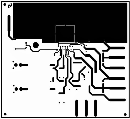
Cheap car subwoofer filter pcb layout:


Cheap car subwoofer filter circuit partlist:

IC1_______________________________M5218A
IC2_______________________________LM7812 IC-regulator 12V
R1, R2, R3_______________47K_______Resistor 1/4W 1%
R4, R5, R6, R7, R10_______10K_______Resistor 1/4W 1%
R8______________________20K_______Resistor 1/4W 1%
R9______________________100 ohm__ Resistor 1/4W 1%
C1, C2, C3, C4, C5________ 4.7uF 63V _see text
C6______________________0.33uF 63V see text
C7______________________0.27uF 50V see text
C8______________________0.027uF 50V see text
C9, C10__________________10uF 16V see text
C11_____________________0.1uF 63V see text
C12_____________________ 100uF 16V Electrolytic Capacitors
C13_____________________ 100uF 25V Electrolytic Capacitors

Searches related to subwoofer filter circuit board

subwoofer filter circuit diagram,
subwoofer filter kit,
subwoofer filter circuit using op-amp tl072,
subwoofer filter circuit for tda7294,
subwoofer filter circuit using lm324,
subwoofer preamp circuit diagram,
diy low pass filter for subwoofer,
simple subwoofer circuit diagram,

Subwoofer Filter Circuit Board

11/07/2017

LM4702 Amplifier Circuit Diagram

LM4702 general description:

     The LM4702 is a high fidelity audio power amplifier driver designed for demanding consumer and pro-audio applications. Amplifier output power may be scaled by changing the supply voltage and number of output devices. The LM4702 is capable of delivering in excess of 300 watts per channel single ended into an 8 ohm load in the presence of 10% high line headroom and 20% supply regulation. The LM4702 includes thermal shut down circuitry that activates when the die temperature exceeds 150°C. The LM4702's mute function, when activated, mutes the input drive signal and forces the amplifier output to a quiescent state. The LM4702 is available in 3 grades that span a wide range of applications and performance levels. The LM4702C is targeted at high volume applications. The LM4702B includes a higher voltage rating along – LM4702A (1) (in development): with the tighter specifications. The LM4702A(1) (in ±20V to ±100V development) is the premium part with the highest voltage rating, fully specified with limits over voltage – LM4702B: ±20V to ±100V and temperature, and is offered in a military 883 – LM4702C: ±20V to ±75V compliant TO-3 package.

LM4702 features:

  • Very High Voltage Operation
  • Scalable Output Power
  • Minimum External Components
  • External Compensation
  • Thermal Shutdown and Mute

LM4702 applications:

  • AV Receivers
  • Audiophile Power Amps
  • Pro Audio
  • High Voltage Industrial Applications

LM4702 circuit diagram:

Typical Audio Amplifier Application Circuit

LM4702 layout and pcb:

LM4702 layout


LM4702 bottom pcb
LM4702 top pcb


Блок питания усилителя

LM4702 Audio Power Amplifier Datasheet - Download


Searches related to LM4702 Amplifier Circuit Diagram

lm4702 bridge amplifier   
lm4702 pcb
lm4702 price
lm4702 equivalent
lm4702 replacement
lm4702 datasheet
1000 watts power amplifier schematic diagram
lm4702 mosfet amplifier

Circuit Archives - Amplifier Circuit Design

Audio Power Amplifier Driver
Audio Power Amplifier Series Stereo High Fidelity 200 Volt ...
MOSFET Bridge Power Amplifier - Forum for Electronics

11/06/2017

TDA7265 subwoofer circuit diagram

TDA7265 description:

     The TDA7265 is class AB dual Audio Amplifier assembled in the multi watt package specially designed for high quality sounds application as Hi-Fi music centers and stereo TV sets

TDA7265 features:


  • WIDE SUPPLY VOLTAGE RANGE (UP TO±25V ABS MAX.)
  • SPLIT SUPPLY
  • HIGH OUTPUT POWER 25 + 25W @ THD =10%, RL = 8Ω, VS = +20V
  • NO POP AT TURN-ON/OFF
  • MUTE (POP FREE)
  • STAND-BY FEATURE (LOW Iq)
  • SHORT CIRCUIT PROTECTION
  • THERMAL OVERLOAD PROTECTION

TDA7265 amplifier circuit:

TDA7265 amplifier circuit

TDA7265 pcb

Searches related to TDA7265tda7265 amplifier circuittda7265 voltagetda7265 subwoofer circuit diagramtda7265 pcb layouttda7265 equivalenttda7265 single supplytda7265 power supplytda7265 amp circuitThe TDA7265 is class AB Dual Audio Power amplifier assembled in the @ Multiwatt package, specially designed for high quality sound application as Hi-Fi 

11/01/2017

TDA2030 Audio Amplifier 1 x40W

TDA2030 general description: 

    Although there are a number of hybrid output modules on the market, very few of them combine compactness with reasonable price and good performance. One of these few is SGS's used in the present amplifier. The design of the amplifier is straightforward: a power op-amp followed by two output transistors. The audio signal is applied to the non-inverting input of power op-amp IC1 TDA2030 via socket K1 and capacitor C1. The supply current to the IC varies in accordance with the input signal. Consequently, there will be a similarly varying voltage drop across resistors R6, R7, R8, and R9 since these are in the supply lines to the op-amp. As long as the current is lower than about 1A, the voltage drop across the resistors will be insufficient to switch on transistors T1 and T2. This means that outputs up to 2 W into 4 ohm are provided entirely by the op-amp. Once the output current exceeds a level of 1A, the transistors are on and contribute to the power output.
When the Input signal is small, there no quiescent current through the transistor, but there is through the op-amp. Crossover problems are thus obviated. Since the IC also provides thermal compensation, stability of the operating point is ensured.
The supply voltage may lie between 12 V and an absolute maximum of 44 V. Construction of the amplifier on the printed-circuit board should be straightforward. The transistors as well as the IC must be fitted insulated on to a heat sink of about 2 k W. Use plenty of heat conducting paste. The supply line should be protected by a 3.15 A fuse. You can use BD911, BD912 for T1 and T2.

TDA2030 Technical Data:


  • Supply voltage  - 44 V
  • Maximum output - 22 W into 8 Ohm
  • Maximum output - 44 W into 4 Ohm

TDA2030 Circuit diagram:

 
TDA2030 circuit diagram

TDA2030 pcb layout:

TDA2030 pcb and layout

TDA2030 parts list:

Resistors:
  • R1-R4 - 100 KOhm
  • R5 - 8.2 KOhm
  • R6 - R9 - 1.4 Ohm, 1%
  • R10 - 1 Ohm

Capacitors:
  • C1 - 470 nF
  • C2 - 10 uF, 63 V, radial
  • C3 - 4.7uF, 63 V, radial
  • C4,C5,C7 - 220 nF
  • C6 - 2200 uF, 50 V, radial
  • C8 - 100 uF, 50 V, radial

Semiconductors:
  • D1, D2 - 1N4001
  • T1 - BD712
  • T2 - BD711
  • IC1 - TDA2030
Datasheet for TDA2030: Download

Searches related to TDA2030


tda2030 circuit,
tda2030 power supply,
tda2030 subwoofer amplifier circuit,
tda2030 pinout,
tda2030 ic,
tda2030 price,
tda2030 pdf,
tda2030 pin configuration,

10/31/2017

LM1875 AUDIO AMPLIFIER 20W

LM1875 general description:


LM1875 pcb layout
LM1875 pcb layout
The LM1875 is a monolithic power amplifier offering very low distortion and high quality performance for consumer audio applications. The LM1875 delivers 20 watts into a 4Ω or 8Ω load on ±25V supplies. Using an 8Ω load and ±30V supplies, over 30 watts of power may be delivered. The amplifier is designed to operate with a minimum of external components. Device overload protection consists of both internal current limit and thermal shutdown.The LM1875 design takes advantage of advanced circuit techniques and processing to achieve extremely low distortion levels even at high output power levels. Other outstanding features include high gain, fast slew rate and a wide power bandwidth, large output voltage swing, high current capability, and a very wide supply range. The amplifier is internally compensated and stable for gains of 10 or greater.


LM1875 amplifier circuit:

LM1875 AUDIO AMPLIFIER 20W

LM1875 power supply diagram:

LM1875 power supply diagram

LM1875 pcb layout:

LM1875 pcb layout
LM1875 pcb layout

LM1875 project review:


Searches related to AUDIO AMPLIFIER 20W

max9744 amplifier
max9744 adafruit
max9744 raspberry pi
20w class d amplifier
max9744 review
max9744 datasheet
arduino controlled audio amplifier

raspberry pi tube amplifier

Search This Blog

Powered by Blogger.

200W Audio Amplifier Circuit

Circuit description: Connecting two TDA2030 thru cheap power transistors we can create a amplifier wich can deliver a higher power. Wi...

Labels

Amplifier Circuits (107) 4 Ω (85) TDA Amplifiers (66) Amplifier (50) 8 Ω (46) Circuit (37) subwoofer (31) Layout (26) audio (26) Subwoofer circuit (25) 2 Ω (23) Class D (23) Subwoofer Amplifier (23) Description (22) PCB (21) Subwoofer Diagram (21) Audio Amplifier (20) Stereo Amplifier (18) 20W (17) Auto Subwoofer (17) Stereo Amp (16) car subwoofer (16) BTL amplifier (14) ClassAB (14) Software (14) Electronic software (13) Sound System (13) 2x10W (12) 4-channel (12) 60W (12) BTL audio amplifier (12) Car Audio (12) Operational Amplifier (12) Power Amplifier (12) 2x12W (10) Audio Power Amplifier (10) Car Stereo (10) 2x25W (9) 5W (9) Car Amplifier (9) Circuit Diagram (9) Dual channel (9) Filter Circuits (9) Speakers (9) 2x40W (8) 2x6W (8) 3W (8) 4x50W (8) Audio Power Amp (8) Class B (8) Guitar Amplifier (8) 10W (7) 2x22W (7) 4x35W (7) 50W (7) Car Stereos (7) Subwoofer car (7) car radio amplifier (7) mono amplifier (7) 100W (6) 12W (6) 1W (6) 2-channel (6) 22W (6) 2w (6) 2x20W (6) 2x30W (6) Features (6) Guitar circuits (6) Microphone (6) Mixer (6) Stereo Preamp (6) general description (6) quad bridge (6) tone control (6) 100W Audio Amplifier (5) 18W (5) 40W (5) 4W (5) 4x45W (5) 6 Ω (5) 70W (5) Amps (5) Audio Processor (5) Car radio (5) Diagram (5) MOSFET (5) Preamplifier (5) applications (5) hi-fi audio power amplifier (5) newamps (5) 15W (4) 2-channel Amplifier (4) 200W (4) 2x100W (4) 2x15W (4) 6W (4) 8W (4) Amplifier High-Performance (4) BTL stereo (4) Bridge Amplifer (4) Class T (4) Datasheet (4) Dual Preamplifier (4) Equalizer circuit (4) Quad power amplifier (4) STK Amplifier (4) Sound Amplifier Circuit (4) Volume Control (4) car radio power amplifier (4) stereo BTL (4) 100W Subwoofer (3) 24W (3) 2x200W (3) 2x50W (3) 3 Ω (3) 3-channel (3) 300W (3) 35W (3) 4-ch amplifier circuit diagram (3) 400W (3) 4x11W (3) 4x12W (3) 4x22W (3) 4x40W (3) 500W (3) 80W (3) AM/FM Tuner (3) Amp (3) Amplifer (3) Arduino (3) Audio Circuit Diagram (3) Audio Speakers (3) Audio signal processing (3) Car Speakers (3) DMOS (3) Digital Audio Amplifier (3) Dual Audio (3) Dual BTL (3) Graphic Equalizer (3) Guitar (3) Guitar Effect Circuit (3) Hi-Fi audio (3) LED (3) Low noise (3) Power Supply (3) STK412-000 (3) Stereo balance meter (3) Subwoofer Design (3) Surround (3) TDA (3) TDA1566 (3) TDA2008 (3) TDA8586 (3) Tips To Save Energy (3) digital controlled (3) guitars (3) single channel (3) stereo headphone (3) 100+100W (2) 1000W (2) 1000W Amplifier (2) 100W Subwoofer Amplifier Circuit (2) 14W (2) 180W + 180W (2) 1ch BTL Power Amplifier (2) 2 x 210 Watt (2) 200W amplifier (2) 25W (2) 28w (2) 2x110W (2) 2x11W (2) 2x120W (2) 2x150W (2) 2x1W (2) 2x210W (2) 2x24W (2) 2x300W (2) 2x35W (2) 2x46W (2) 2x5W (2) 2x7W (2) 2x80W (2) 3 channel amplifier (2) 30W (2) 30w Amplifier (2) 32 Ω (2) 32W (2) 45W (2) 4x13W (2) 4x25W (2) 4x30 (2) 4x6W (2) 4x70W (2) 5 Band Graphic Equalizer Circuit (2) 92W (2) AM receiver (2) AM/FM Radio (2) AN12941A (2) AN12972A (2) AN7110 (2) AN7163 (2) AN7177 (2) AN7531SA (2) ARM (2) ARM Microcontroller (2) Aliexpress circuits (2) Amplifier Transistors (2) Audio Filter Circuits (2) Audio Mixer (2) Audio Mixer Circuit (2) Audio Preamplifier (2) BCDMOS technology (2) BTL power amplifier (2) CMOS (2) Car Subwoofers (2) Ceiling Speakers (2) Class H (2) Equalizer (2) FM Stereo (2) FM Transmitter (2) Guitar Amps (2) Guitar circuit (2) HA13116 (2) Hi-Fi systems (2) IRF530 (2) IRF9530 (2) LA4460N (2) LM1875 (2) LM380 (2) LM3886 (2) LPC2124 (2) MOSFET Audio Amplifier (2) Microcontroller (2) Music System (2) NE5532 (2) NE555 (2) Peak Indicator (2) Power Amp (2) Recording (2) STA501 (2) STEREO (2) STK400-530 (2) Sound (2) Sound Decoder (2) Speaker (2) Stereo Decoder (2) Stereo Headphone Amplifier (2) TA8210AH Amplifier (2) TDA1015 (2) TDA1037 (2) TDA1083 (2) TDA1514A (2) TDA1517 (2) TDA1562Q (2) TDA1904 (2) TDA1905 (2) TDA1910 (2) TDA2003 (2) TDA2004 (2) TDA2051 (2) TDA2613 (2) TDA7056 (2) TDA7264 (2) TDA7269 (2) TDA7294 (2) TDA7298 (2) TDA7299 (2) TDA7334 (2) TDA7360 (2) TDA7454 (2) TDA7481 (2) TDA7490 (2) TDA7511 (2) TDA7850 (2) TDA8562Q (2) TDA8922 (2) TDA8924 (2) TDA8929T (2) TDA8931 (2) Two-channel Amplifier (2) best car speakers (2) demodulators FM (2) high performance hi-fi amplifier (2) partlist (2) quad bridge car radio amplifier (2) speaker protection (2) stereo car radio power amplifier (2) stereo tv (2) subwoofer circuit diagram (2) subwoofer for car (2) subwoofer preamp circuit diagram (2) subwoofers for cars (2) /Playback Pre-/Power Amplifier (1) 0.5W (1) 1 Ω (1) 1-channel (1) 1.2W (1) 1.6W (1) 10+10+10W (1) 1000 watts power amplifier schematic diagram (1) 1000W MOSFET (1) 100W Guitar Amplifier (1) 100W MOSFET (1) 10W circuit (1) 10W+10W (1) 1100W (1) 12 W car radio power amplifier (1) 1200W (1) 120W (1) 13.5W (1) 130W (1) 140 watt subwoofer (1) 140W (1) 14W+2x7.5W (1) 150 Amplifier (1) 150W (1) 150W+150W+150W (1) 170W amplifier (1) 17W (1) 18W Class-B Audio Amplifier (1) 19V (1) 1Kw Amplifier (1) 2 × 13 W (1) 2.1 channel (1) 2.7W (1) 200 Watts Amplifier Circuit (1) 200 watt mosfet amplifier circuit (1) 200W Audio Amplifier Circuit Diagram (1) 200W amplifier circuit (1) 200w stereo digital audio power amplifier (1) 20W+20W (1) 20W+20W+20W (1) 21W (1) 240W (1) 26 W BTL (1) 26V (1) 27W (1) 2SK1066 (1) 2x1.4W (1) 2x1.7W (1) 2x1100W (1) 2x13W+26W (1) 2x14W (1) 2x170W (1) 2x175W (1) 2x18W (1) 2x2.2W (1) 2x23W (1) 2x250W (1) 2x2W (1) 2x32W (1) 2x45W (1) 2x5.5W (1) 2x500W (1) 2x60W (1) 2x60mW (1) 2x7.3W (1) 2x70W (1) 2x75mW (1) 3 band equalizer guitar (1) 3-channel mixer (1) 30 Watt x 5 (1) 300W Subwoofer (1) 300W Subwoofer Power Amplifier (1) 315W (1) 32W Stereo (1) 350 watt mono amplifier (1) 35mW (1) 3x10W (1) 3x150W (1) 3x20W (1) 3x90Watt (1) 4 channel amplifier (1) 4 channel audio amplifier circuit diagram (1) 4 channel car amplifier circuit (1) 4 × 13 W (1) 4-Channel Outputs Volume Tone Balance (1) 4.4W (1) 4.5W (1) 400W IRFP448 (1) 40W Amplifier (1) 430mW (1) 43W (1) 4461N (1) 44W (1) 47W (1) 4x100W (1) 4x15W (1) 4x20W (1) 4x30W (1) 4x33W (1) 4x34W (1) 4x37W (1) 4x38W (1) 4x42W (1) 4x43W (1) 4x44W (1) 4x46W (1) 4x47W (1) 4x6.5W (1) 4x60W (1) 4x75W (1) 4x7W (1) 4Ω (1) 5 channel amplifer (1) 5-band stereo (1) 5.1 subwoofer circuit diagram (1) 5.4W (1) 5.5W (1) 5.8W (1) 55 dB (1) 56W (1) 5W+5W (1) 60 Watt (1) 60W Hi-Fi Power Amplifier Circuit (1) 60W+60W (1) 6x30W (1) 7 segment display Arduino (1) 7.5W (1) 70 Watt MOSFET Audio Power Amplifier (1) 70V (1) 75W (1) 7W (1) 80W Subwoofer (1) AA (1) AAA (1) AC and DC (1) AD1991 (1) AD199x (1) ADC (1) ADDR (1) ALC circuit (1) AM Radio Circuits (1) AM Tuner (1) AM tuner RF amplifier (1) AM-demodulator (1) AM/FM (1) AN17000A (1) AN17810 (1) AN17813A (1) AN17831A (1) AN17850A (1) AN4250 (1) AN4558 (1) AN5275 (1) AN5277 (1) AN5279 (1) AN7060 (1) AN7086S (1) AN7112 (1) AN7116 (1) AN7124 (1) AN7125 (1) AN7131 (1) AN7134 (1) AN7147 (1) AN7148 (1) AN7158N (1) AN7161 (1) AN7164 (1) AN7170 (1) AN7176 (1) AN7176K (1) AN7190 (1) AN7190NK (1) AN7195 (1) AN7198 (1) AN7208SA (1) AN7273 (1) AN7310N (1) AN7337N (1) AN7500FHQ (1) AN7504SB (1) AN7510 (1) AN7511 (1) AN7512 (1) AN7515SH (1) AN7516SH (1) AN7551Z (1) AN7555NZ (1) AN7560 (1) AN7561Z (1) AP130 (1) AP4809 (1) APA2065 (1) Altium Designer (1) Am Radio (1) Amplifier Circuit diagram (1) Amplifier Circuit for TV (1) Amplifier Features (1) Amplifier circuit (1) Amplifiers circuits (1) Arduino Uno Rev3 schematic (1) Audio Car (1) Audio Codec (1) Audio Equalizer (1) Audio IC (1) Audio Power Circuit LM Amplifiers (1) Audio Procesor (1) Audio Systems (1) Auto Radio (1) Auto Reverse (1) BA10324A (1) BA10324AF (1) BA10324AFV (1) BA1442A (1) BA328 (1) BA3306 (1) BA3430S (1) BA3826S (1) BA3837 (1) BA3840KV (1) BA3842 (1) BA3853 (1) BA3870 (1) BA3880 (1) BA5204 (1) BA5210FS (1) BA5406 (1) BC 547B (1) BCD technology (1) BICMOS (1) BTL car audio (1) BTL/SE (1) BTSC (1) BUZ23 (1) Basic Low Power AM transmitter (1) Bass (1) Bass Amplifier (1) Bass Boost System (1) Bass Guitar (1) Battery Level Indicator (1) Bridge-Tied Load (1) Build A Subwoofer Box (1) Building subwoofer (1) CS44130 (1) Cable Set-Top Products (1) Car Subwoofer Amplifier Circuit Diagram (1) Car audio amplifier with IC TA7203P (1) Center-Channel (1) Circuit Mixer (1) Circuit Simulator (1) Class T amplifiers (1) Class-B (1) Class-D (1) Clipping Detector (1) Computer Speaker (1) DDD (1) DDX-2060 (1) DIL (1) DMOS Audio Amplifier (1) DTL (1) DVCs (1) DVD Receivers (1) Denon Subwoofers (1) Design a Subwoofer Box (1) DesignSpark PCB (1) Detector (1) Diagram mixer (1) Diference Amplifier (1) Differentiator (1) Digital Delay (1) Digital Echo (1) Digital Radio (1) Digital TV (1) DipTrace (1) Dual Audioprocessor (1) Dual Pre Amplifier (1) Dual amplifier (1) Dual operational amplifier (1) Dynamic Distortion Detector (1) EDWinXP (1) EUA5202 (1) Eagle (1) Easy to Make (1) Electric Motor (1) Electricity (1) Electronic Componets (1) Equalized-preamp (1) ExpressPCB (1) FET (1) FM demodulator (1) FM processing (1) FM radio (1) FM radio Receivers (1) FM receivers (1) FM sound (1) FM stereo decoder (1) FM tuners (1) FOUR CHANNEL (1) FreePCB (1) Guitar Amp Circuit (1) Guitar Amplifier Circuit (1) Guitar pre-amplifier (1) Guitar vocal adaptor amp (1) HA12002 (1) HA13117 (1) HA13118 (1) HA13119 (1) HA13127 (1) HA13150A (1) HA13151 (1) HA13153 (1) HA13155 (1) HA13156 (1) HA13158A (1) HA13159 (1) HA1397 (1) HDMI (1) HEXFET (1) Headphone (1) High Gain (1) High Signal-to-Noise ratio (1) How to Build a Subwoofer Box (1) How to Match a Car Subwoofer (1) I2C Bus Interface (1) IF Amplifier (1) IF-PLL (1) IF-PLL demodulator (1) IRFP260 (1) ISS filter (1) Integrator (1) Inverting (1) It begins with your commitment (1) KA22134 (1) Kicad (1) LA3160 (1) LA4440 (1) LA4445 (1) LA4446 (1) LA4500 (1) LA4558 (1) LA4625 (1) LA4628 (1) LA4725 (1) LM Series (1) LM101 (1) LM101A (1) LM12 (1) LM2002 (1) LM2005 (1) LM378 (1) LM383 (1) LM383A (1) LM386 (1) LM386N (1) LM3876 (1) LM391 (1) LM4732 (1) LM4766 (1) LM4851 (1) LM567 Infrared Transmitter Circuit (1) LM6161 (1) LM6261 (1) LM6361 (1) LM833 (1) LS404 (1) LX1720 (1) Line Level Stereo (1) Loudspeaker (1) Low Noise Amplifier (1) Low distortion (1) M65831A (1) MC1350 (1) MJE340 (1) MJE350 (1) MOSFET power amplifier (1) MOSFET quad bridge (1) Microphone System (1) Mini Portable Guitar Amplifier (1) Mitsubishi M5226P (1) Mobile Car Stereo Amplifier (1) Modulated Receiver (1) Mp3 Player (1) Mtx Audio (1) Multi-channel (1) NCP2890 (1) NE 5532 (1) NTE1285 (1) NTE1371 (1) NTE1373 (1) NTE7011 (1) NTE7059 (1) Noise Transistor (1) Offset (1) Overload (1) P-CAD (1) PA03 (1) PA03A (1) PA05 (1) PCB mixer (1) PLL Stereo (1) PLL synthesizer (1) PNP-NPN (1) PWM processor (1) Peamp circuit (1) Phase Locked Loop (PLL) (1) Phono/line adapter (1) Power (1) Power Audio (1) Power Comparator (1) Power Stage Amplifier (1) Preamp Circuit (1) Proteus (1) Pulse Generator (1) Pulse-Frequency (1) Quad Half-Bridge (1) Quad Operational Amplifier (1) RDA Demodulator (1) RDS (1) RDS Filter (1) RF (1) Radio Players (1) Remote amplifier dsp (1) SA58631 (1) SA58632 (1) SA58672 (1) SAP Decoder (1) SAVING ENERGY (1) SCART channel (1) SEPP (1) SMA428A (1) ST-BY (1) STA001 (1) STA323W (1) STA502 (1) STA5100 (1) STA515 (1) STA5150 (1) STA516B (1) STA517B (1) STA7056 (1) STA7575 (1) STK442-130 (1) STK084 (1) STK086G (1) STK400-030 (1) STK4017 (1) STK4044 (1) STK4048 (1) STK4050 (1) STK4050V (1) STK413-000 (1) STK4221 (1) STK433-330 (1) STK433-330N-E (1) STK443-090 (1) STK465 (1) Signal (1) Single Channel Amplifier (1) Six-Channel (1) Sofware (1) Sound Control (1) Sound Demodulator (1) Sound Processor (1) Spectrum Analyzer (1) Sprint-Layout (1) Stand-by options (1) Stereo 300W Audio Amplifier (1) Stereo Audio Amplifier System (1) Stereo Car Audio Amplifie (1) Stereo Demodulator (1) Stereo Digital (1) Stereo Inputs (1) Stereo Radio Circuit (1) Stereo System (1) Stereo System Ic (1) Stereo applications (1) Stereo balance tester (1) Stereo modulator (1) Stereo stk013 audio amplifier circuit (1) Subwoofer 400W (1) Subwoofer output (1) Summing (1) Surround Sound Matrix (1) TA Series (1) TA0102A (1) TA0103A (1) TA0105A (1) TA2022 (1) TA2024C (1) TA3020 (1) TA8159FN (1) TA8220H (1) TA8225H (1) TA8233H (1) TA8238K (1) TA8246AH (1) TA8251AH (1) TA8255AH (1) TA8260 (1) TA8263 (1) TA8273 (1) TA8276H (1) TA8277 (1) TAA4100 (1) TAS5122 (1) TAS5132 (1) TB2903HQ (1) TDA 1524A (1) TDA Amplifier Circuit (1) TDA1001B (1) TDA1010A (1) TDA1011 (1) TDA1013B (1) TDA1016 (1) TDA1020 (1) TDA1308 (1) TDA1400 (1) TDA1510 (1) TDA1512 (1) TDA1515 (1) TDA1516 (1) TDA1518 (1) TDA1519 (1) TDA1520A (1) TDA1521 (1) TDA1523 (1) TDA1524 (1) TDA1526 (1) TDA1552Q (1) TDA1554Q (1) TDA1555Q (1) TDA1556Q (1) TDA1557Q (1) TDA1558Q (1) TDA1560Q (1) TDA1561Q (1) TDA1563Q (1) TDA1564 (1) TDA1565 (1) TDA1572 (1) TDA1599 (1) TDA1908 (1) TDA2002 (1) TDA2005 (1) TDA2006 (1) TDA2007 (1) TDA2009A (1) TDA2020 (1) TDA2025 (1) TDA2030 (1) TDA2040 (1) TDA2050 (1) TDA2052 (1) TDA2075 (1) TDA2075A (1) TDA2320A (1) TDA2500 (1) TDA2611 (1) TDA2611A (1) TDA2614 (1) TDA2615 (1) TDA2616 (1) TDA2822 (1) TDA3803 (1) TDA7050T (1) TDA7052 (1) TDA7231A (1) TDA7245 (1) TDA7250 (1) TDA7253 (1) TDA7256 (1) TDA7261 (1) TDA7262 (1) TDA7263 (1) TDA7263M (1) TDA7266 (1) TDA7266B (1) TDA7267 (1) TDA7268 (1) TDA7269A (1) TDA7293 (1) TDA7295 (1) TDA7296 (1) TDA7296A (1) TDA7297 (1) TDA7310 (1) TDA7313 (1) TDA7317 (1) TDA7318 (1) TDA7319 (1) TDA7330B (1) TDA7332 (1) TDA7336 (1) TDA7338 (1) TDA7339 (1) TDA7348 (1) TDA7350 (1) TDA7365 (1) TDA7370 (1) TDA7374 (1) TDA7374B (1) TDA7375 (1) TDA7376B (1) TDA7377 (1) TDA7381 (1) TDA7382 (1) TDA7383 (1) TDA7384A (1) TDA7385 (1) TDA7388 (1) TDA7391 (1) TDA7393 (1) TDA7394 (1) TDA7396 (1) TDA7430 (1) TDA7433 (1) TDA7443 (1) TDA7451 (1) TDA7462D (1) TDA7468 (1) TDA7469 (1) TDA7476 (1) TDA7480 (1) TDA7482 (1) TDA7494 (1) TDA7495 (1) TDA7496 (1) TDA7497 (1) TDA7497S (1) TDA7499 (1) TDA7502 (1) TDA7560 (1) TDA7561 (1) TDA7562 (1) TDA7563 (1) TDA7563B (1) TDA7564 (1) TDA7564B (1) TDA7565 (1) TDA7566 (1) TDA7567 (1) TDA7572 (1) TDA7575 (1) TDA7594 (1) TDA8426 (1) TDA8496 (1) TDA8510J (1) TDA8511J (1) TDA8512J (1) TDA8542 (1) TDA8543 (1) TDA8547 (1) TDA8551 (1) TDA8552T (1) TDA8552TS (1) TDA8559T (1) TDA8560Q (1) TDA8561Q (1) TDA8563AQ (1) TDA8564Q (1) TDA8565Q (1) TDA8566 (1) TDA8566TH1 (1) TDA8568Q (1) TDA8569Q (1) TDA8571J (1) TDA8576 (1) TDA8580 (1) TDA8581 (1) TDA8588J (1) TDA8591 TDA8591J (1) TDA8593J (1) TDA8594 (1) TDA8595 (1) TDA8596 (1) TDA8851 (1) TDA8920 (1) TDA8925 (1) TDA8926J (1) TDA8927 (1) TDA8927/TDA8929 (1) TDA8928 (1) TDA8932 (1) TDA8932B (1) TDA8943 (1) TDA8944 (1) TDA8946 (1) TDA8947J (1) TDA8950 (1) TDA8954 (1) TDA9610H (1) TDA9821 (1) TDA9830 (1) TDA9847 (1) TDA9852 (1) TDA9853H (1) TDA9861 (1) TDA9873 (1) TDA9874 (1) TDA9875 (1) TDA9880 (1) TDA9887 (1) TDB7910 (1) TEA6360 (1) TL071 (1) TL072 (1) TMPA401DM (1) TOP 10 (1) TP2350B (1) TPA2000D2 (1) TPA3122D2 (1) TTL (1) TV (1) TV application (1) TV sound processor (1) TV/FM (1) Telephone Headphone (1) Thermal Shutdown (1) Thermal protector (1) Tone Control Circuit (1) Tone Controls (1) Tone-Control (1) TopoR (1) Triple Amplifier (1) Tunable bandpass filters variable resistors (1) UART (1) UPC1230H2 (1) USB Powered Stereo (1) VCRs (1) VTR (1) VU Level (1) VU meter (1) Vocal Fader (1) Voice Canceller (1) Voltage (1) Voltage Converter (1) Wire (1) Wireless (1) Wireless am microphone (1) acoustic guitar (1) amplifier for headphone (1) audio HDMI interface (1) audio panoramic interface (1) audio power amplifier ic (1) ba526 (1) band-pass (1) bass boost amplifiers (1) battery (1) cheap guitar amps (1) circuit Schematic (1) computer speakers (1) decoder Circuit (1) demodulators AM (1) diagnostic facility (1) effects loop guitar (1) electric guitar (1) electronic project (1) fault protection (1) filter-free class-D (1) gibson guitars (1) guitar amp amazon (1) guitar amp marshall (1) guitar amp reviews (1) guitar amplifier olx (1) guitar amplifier price (1) guitar amps brands (1) guitar ams (1) guitar parts (1) guitar tube amps (1) ha13128 (1) headphone amplifier circuit using op-amp (1) high-performance (1) home audio amplifier (1) ic (1) lights upon detection (1) lm4702 bridge amplifier (1) lm4702 datasheet (1) lm4702 equivalent (1) lm4702 mosfet amplifier (1) lm4702 pcb (1) lm4702 price (1) lm4702 replacement (1) load detection (1) low pass subwoofer circuit diagram (1) low voltage (1) magnet (1) mono BTL amplifier (1) mono bridge amplifier (1) mosfet amplifier circuit for subwoofer (1) mosfet power amplifier circuit (1) muting (1) new amp (1) nte1165 (1) ohmmeter arduino (1) outdoor speakers (1) pc speakers (1) playback (1) po (1) power amplifier with distortion detector (1) power guitar amplifier (1) preamp gain guitar (1) satellite (1) simple headphone amplifier circuit (1) single-in-line (1) sound decoder circuit (1) speaker stands (1) stereo 175 watt amplifier (1) stereo VU meter (1) stereo headphone amplifier circuit (1) stereo indicator (1) stereo power meter (1) stereo tone control (1) stereo tube amplifier (1) subwoofer circuit diagram pdf (1) subwoofer design software (1) subwoofer filter board (1) subwoofer filter circuit diagram (1) subwoofer filter circuit for tda7294 (1) subwoofer filter circuit using lm324 (1) subwoofer filter circuit using op-amp tl072 (1) subwoofer filter kit (1) subwoofer filter subwoofer filter circuit using lm324 (1) subwoofers and amplifiers (1) symmetrical power supply (1) tda2030 circuit (1) tda2030 ic (1) tda2030 pdf (1) tda2030 pin configuration (1) tda2030 pinout (1) tda2030 power supply (1) tda2030 price (1) tda2030 subwoofer amplifier circuit (1) tda7265 amp circuit (1) tda7265 amplifier circuit (1) tda7265 equivalent (1) tda7265 pcb layout (1) tda7265 power supply (1) tda7265 single supply (1) tda7265 subwoofer circuit diagram (1) tda7265 voltage (1) tda8946j equivalent (1) tda8947j circuit diagram (1) tda8947j equivalent (1) tda8947j pinout (1) tda8947j price (1) tda8947j schematic (1) two-channel audio amplifier (1) uPC1032H (1) uPC1188H (1) voltage regulator (1)